Description
The DBB (Double Block and Bleed) Plug Valve is designed to provide safe and reliable double isolation in pipeline systems handling hazardous and high-permeability media. Its guided rail-type plug structure reduces sealing surface wear and ensures long service life. The double sealing design effectively prevents leakage, while the self-locking operating mechanism allows smooth and stable operation. Special surface treatments improve corrosion and wear resistance. Integrated cavity pressure relief systems enhance operational safety.
Features
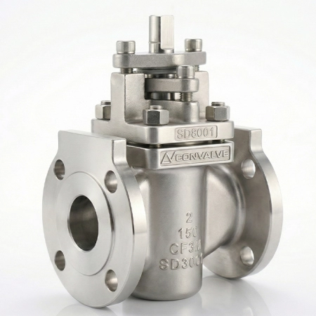
- Middle flange double seal structure The middle flange double seal structure rail plug valve is mostly used for aviation kerosene, natural gas, liquefied petroleum gas, product oil, etc. Because aviation kerosene and other media have strong permeability and are flammable and explosive, in order to prevent leakage of the medium, the middle flange uses an O-ring and winding gasket double seal structure.
- Packing seal structure The orbital plug valve spool moves both vertically and rotationally during the valve switching process. Considering the particularity of the medium, in order to ensure the packing seal is safe and reliable, a combination of O-ring and packing seal is used.
- Operating mechanism of the valve and self-locking The plug valve operating mechanism (screw type) adopts a unique L-shaped slot structure. It allows the plug to move axially and rotate 90° separately, making the valve operation flexible and lightweight.
- Special processing of key parts Valve body cavity: Mechanically processed (grinding) and treated with hard chrome plating, making the valve cavity resistant to corrosion, erosion, and wear.
-
- Slide block: After mechanical processing (before pressing fluorine rubber), the slide block metal sealing surface is treated with hard chrome plating, providing corrosion, erosion, and wear resistance.
- Plug: After mechanical processing, nickel plating is applied, improving corrosion resistance of the plug and the upper and lower shafts.
- Valve stem: After rough machining, the valve stem is tempered, and the surface hardness after finishing is no less than 900 HV, improving anti-galling and wear resistance of the screw sleeve.
- Guide groove and key: The L-shaped guide groove and the guide key head on the screw sleeve are processed and quenched to no less than 45 HRC, improving wear resistance and ensuring that the guide key can slide freely in the guide groove.
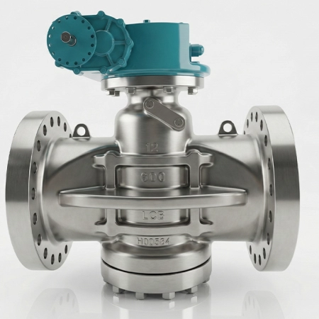
- Online adjustment and maintenance of packing The track plug has windows for adjustment and maintenance of packing on both sides of the support.
- Integral plug structure The plug of the track plug valve adopts an integral casting structure. The plug is integrated with the upper and lower axes. When unidirectional compression is applied, it ensures that the upper and lower axes have enough rigidity, strength, and bending resistance.
- Valve cavity overpressure relief function The pressure difference is caused by changes in environmental temperature. A double-sealed valve in the closed state experiences volume expansion of the medium as ambient temperature rises, gradually increasing pressure. If the pressure difference is not released in time, it can seriously impact valve operation or even cause valve cracking, posing a hidden safety risk. Rail plug valves usually have three relief systems:
-
- Manual pressure relief system For manual operation of the valve. Usually, needle-type valves are mounted on the valve body. When the valve is closed, open the pressure relief valve in the middle chamber to release the medium to the upstream pipeline or atmosphere (to check the sealing effect if releasing to the atmosphere).
- Differential pressure relief system For manual and electric operation of valves. A piping system with a check valve is used. The isolation valve is usually open. When the valve is closed, the one-way valve (check valve) in the body relieves pressure to the upstream valve and pipe. At the same time, the manual release valve can be opened to test the sealing effect. When the valve is opened, the manual release valve must be closed.
- Automatic pressure relief system For electrically operated valves. When the valve is closed, the pressure relief valve will open automatically through the operating mechanism, connecting the valve chamber with the upstream pipeline or the outside.
Specifications
THE TECHNICAL SPECIFICATION
| ITEM | SPECIFICATION |
| Structure form | BC |
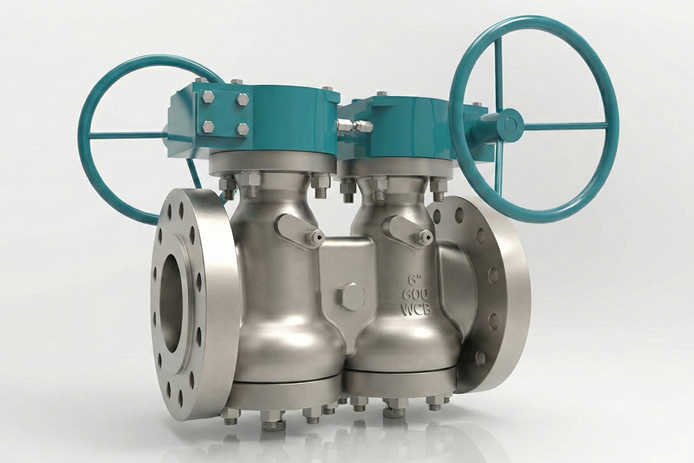
| Drive mode | Manual, Electric, Pneumatic |
| Design criteria | API6D / API599 / BS5353 / GB / T122130 |
| Structural length standard | API6D / ASME B16.10 / EN558 |
| Flange connection standard | ASME B16.5 / EN1092 / HG / T20592 |
| Welding connection standard | ASME B16.25 / BS6.10 |
| NPT connection standard | ASME B1.20.1 |
| Pressure temperature rating | ASME B16.34 |
| Inspection standard | API6D / API598 |
| Fire protection standard | API607 |
PRODUCT PERFORMANCE SPECIFICATION
| NOMINAL PRESSURE (LB) | SHELL TEST PRESSURE (MPA) | SEAL TEST PRESSURE (MPA) | SUITABLE TEMPERATURE (°C) | APPLICABLE MEDIUM |
| 150 | 3.0 | 2.2 | < 180°C | Water, Steam, Oil |
| 300 | 7.5 | 5.5 | ||
| 600 | 15.0 | 11.0 | ||
| 900 | 22.5 | 16.5 |