INTRODUCTION: GATE VALVES VS. BUTTERFLY VALVES

In piping systems, flow control is a critical factor influencing efficiency, safety, and maintenance costs. The type of valve used plays a direct role in the overall performance of the system. Two of the most commonly used valves in the industry are gate valves and butterfly valves.

Gate valves operate with a linear motion, opening or closing the flow path completely. When fully open, they provide minimal flow resistance. However, they are often large and heavy, adding extra load to the pipeline and requiring more complex installation.

Butterfly valves, on the other hand, control flow through a rotating disc positioned in the center of the pipe. A simple 90° turn opens or closes the valve, making them lightweight, cost-effective, and easy to install. Their use in place of gate valves has been increasing steadily in modern industries.

WEIGHT AND INSTALLATION ADVANTAGES

Gate valves, especially in large diameters, can be extremely heavy. For example, a DN1000 gate valve can weigh hundreds of kilograms, requiring additional structural supports. This increases both installation time and total project cost.

Butterfly valves of the same size and pressure class are significantly lighter—sometimes by up to 60%. This reduces the load on the pipeline, minimizes the need for heavy lifting equipment, and simplifies handling during installation. Their compact design also makes them ideal for space-constrained environments such as ships, industrial plants, and energy facilities.

COST AND MANUFACTURING EFFICIENCY

Butterfly valves have a simpler construction with fewer components, making them more economical to produce. This results in lower purchase costs, especially for large-diameter applications. Additionally, their lighter weight reduces transportation and handling expenses.

In some large-scale projects, replacing gate valves with butterfly valves can reduce the overall budget by 20–40%. Convalve offers a wide range of materials (cast iron, ductile iron, stainless steel) and sealing options to meet specific application and budget requirements.

QUICK OPERATION AND FLOW CONTROL

Gate valves require multiple turns to fully open or close, which can be time-consuming in emergencies. Butterfly valves, with their quarter-turn operation, can be opened or closed almost instantly, allowing for rapid intervention in critical situations such as leaks or fire hazards.

They also allow for partial opening, enabling precise flow regulation. While gate valves are generally used in fully open or fully closed positions, butterfly valves can operate in intermediate positions, making them suitable for throttling applications.

MAINTENANCE AND DURABILITY

With fewer moving parts and a straightforward mechanism, butterfly valves require less maintenance. They are less prone to internal corrosion or debris build-up, reducing the risk of operational failures.

Convalve butterfly valves are available with EPDM, NBR, Viton, or metal seals, ensuring reliable performance across a wide range of temperatures and pressures. High-grade materials offer excellent resistance to corrosive media, making them ideal for seawater, chemical processing, and high-pressure applications.

LIMITATIONS AND APPLICATION BOUNDARIES

Although butterfly valves offer numerous advantages, there are scenarios where gate valves may still be preferable—such as in very high-pressure applications (PN40 and above) or when absolute zero leakage is required.

It’s also worth noting that, due to the presence of the disc in the flow path, butterfly valves can introduce a slight pressure drop even in the fully open position. However, modern designs and advanced sealing technology have minimized this drawback.

CONVALVE SOLUTIONS AND PROJECT REFERENCES

With over 20 years of experience, Convalve provides high-performance butterfly valve solutions for a wide range of industrial applications. Our products are trusted in projects across Europe, the Middle East, Africa, and Asia.

Real Project Examples:

  • Turkey – Thermal Power Plant: DN800 butterfly valves extended maintenance intervals by 35%.
  • UAE – Seawater Desalination Plant: Stainless steel, PTFE-sealed butterfly valves eliminated corrosion problems.
  • Netherlands – Port Facility: Switching from gate valves to butterfly valves reduced project costs by 28%.

CONCLUSION

Choosing the right valve for a piping system directly impacts efficiency, maintenance requirements, and safety. With their lightweight design, cost savings, fast operation, easy maintenance, and flow control capabilities, butterfly valves present a strong alternative to traditional gate valves.

Backed by Convalve’s expertise and proven track record, our butterfly valve solutions provide long-term reliability and performance in both new installations and system upgrades.

THE DEMANDS OF MODERN FILLING MACHINES

In today’s fast-paced production environments, filling machines are essential to industries such as beverage bottling, pharmaceutical packaging, cosmetics production, and chemical processing. These machines operate at extremely high speeds, often performing thousands of filling cycles per hour with consistent precision.

Actuated valves – controlled by pneumatic or electric actuators – are vital in these systems. They regulate the flow of liquids into bottles, cans, or containers with exceptional accuracy. In high-speed filling applications, the valve opening and closing frequency is far greater than in most industrial processes, making durability a top priority.


WHY QUALITY MATTERS: DURABILITY UNDER EXTREME CYCLES

While standard valves in many applications might operate only a few times an hour, filling machine valves may cycle tens of thousands of times daily. Low-quality valves quickly wear out, causing downtime, costly repairs, and production losses.

Convalve actuated valves are designed for these extreme demands. Key benefits include:

  • Exceptional Cycle Life – Maintains performance after millions of cycles.
  • Fast Response – Precise filling volumes at maximum production speed.
  • Corrosion and Chemical Resistance – Handles a variety of liquids, from water to aggressive chemicals.
  • Hygienic Design – Meets international sanitary standards for food, beverage, and pharmaceutical production.

These features improve uptime, reduce maintenance, and ensure consistent product quality.


CONVALVE: SETTING THE STANDARD FOR PERFORMANCE

Manufacturers worldwide rely on Convalve actuated valves for reliable filling operations. In beverage plants, our pneumatic actuated ball valves achieve unmatched cycle life, while in pharmaceutical facilities, our butterfly valves ensure contamination-free dosing.

When selecting actuated valves for high-speed filling machines, consider:

  1. Cycle Life Rating – Ability to handle the intended operational cycles.
  2. Actuator Compatibility – Integration with plant automation.
  3. Material and Seal Quality – Match to liquid properties.
  4. Ease of Maintenance – Minimize downtime.

With precision engineering and strict quality control, Convalve is recognized as one of the best valve brands globally. For high-speed filling applications, our actuated valves deliver productivity, reliability, and profitability.

THE RISE OF SMART BUILDING TECHNOLOGY

Smart building systems are transforming the way residential, commercial, and industrial properties are managed. By integrating automation, IoT (Internet of Things) technology, and advanced control systems, smart buildings improve energy efficiency, safety, and convenience for occupants. One of the most critical yet often overlooked components in these systems is the automated valve.

Automated valves in smart buildings enable precise control over water, heating, and cooling systems, contributing to better resource management and enhanced safety. These valves are integrated with sensors, controllers, and building management systems to respond automatically to changing conditions.


MINI MOTORIZED BALL VALVES: COMPACT AND POWERFUL

Among the various valve solutions used in smart buildings, mini motorized ball valves have become increasingly popular. Convalve supplies high-quality mini motorized ball valves that are widely used in domestic water supply systems. A common application is installing these valves immediately after the water meter in new homes.

In combination with leak detection sensors placed in wet areas such as bathrooms, kitchens, and laundry rooms, these valves provide an effective safeguard against water damage. If a sensor detects the presence of water – indicating a leak or flood risk – the mini motorized valve automatically shuts off the water supply, preventing costly damage and protecting property.

Key advantages of Convalve mini motorized ball valves include:

  • Compact Size – Easy to install even in tight spaces.
  • Fast and Reliable Operation – Immediate shut-off when triggered by sensors.
  • Long Service Life – Durable materials ensure years of trouble-free use.
  • Low Power Consumption – Energy-efficient motors ideal for smart building integration.

EXPANDING APPLICATIONS IN SMART BUILDINGS

Beyond flood prevention, automated valves play a role in many other smart building applications:

  • Heating and Cooling Systems – Automatically regulate flow to optimize comfort and energy use.
  • Irrigation Control – Manage outdoor landscaping with weather-based automation.
  • Fire Protection Systems – Control water supply in sprinkler systems for safety and reliability.

Convalve’s range of automated valves has been implemented in projects worldwide, from luxury residential complexes to commercial high-rises. By combining high-quality engineering with seamless automation integration, Convalve ensures smart building systems operate efficiently, safely, and reliably.

THE ROLE OF VALVES IN TEXTILE MACHINERY

The textile industry relies on complex machinery for processes such as weaving, dyeing, finishing, and printing. Among these, dyeing machines stand out for their intensive use of valves. In these systems, valves control the flow of water, steam, and chemicals, ensuring precise process control and consistent product quality.

Dyeing operations require rapid and accurate adjustments in temperature, chemical dosing, and water circulation. This demands valves that can operate reliably under high-frequency use and harsh operating conditions.

HARSH OPERATING CONDITIONS: HEAT AND CORROSION

Valves in textile dyeing machines face two significant challenges: high temperatures and corrosive environments. Steam heating processes can expose valves to extreme heat, while dyeing chemicals, salts, and detergents create highly corrosive conditions.

Two valve types are most commonly used in these applications:

  • Angle Seat Valves – Known for their fast actuation, excellent flow rates, and durability under high-temperature steam and liquid service. Ideal for automated control in textile processing lines.

  • Butterfly Valves – Used for larger pipelines, offering efficient on/off control and throttling capabilities. When made from corrosion-resistant materials, they provide long service life in harsh dyeing environments.

Convalve angle seat and butterfly valves are engineered with high-grade stainless steel, PTFE seals, and advanced actuator technology to withstand both thermal stress and chemical attack.

CONVALVE’S EXPERIENCE IN TEXTILE INDUSTRY PROJECTS

For decades, Convalve has supplied robust valve solutions to textile manufacturers around the world. Our valves are trusted in:

  • Large-scale dyeing plants in Asia, where precise temperature and chemical control are essential for fabric quality.

  • European textile finishing facilities using Convalve butterfly valves in high-capacity water circulation systems.

  • Integrated textile mills in the Middle East relying on angle seat valves for automated, high-speed dyeing operations.

By combining corrosion resistance, thermal durability, and reliable automation, Convalve valves help textile producers achieve consistent quality, maximize uptime, and reduce maintenance costs.

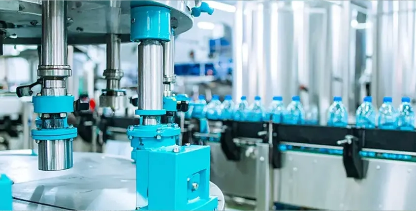
Choosing the right valve is a critical decision in any industrial process, directly impacting safety, efficiency, and long-term operational costs. The vast array of valve types, materials, and configurations can be overwhelming, especially when specific applications and process requirements are taken into account. Understanding the fundamentals of valve selection is essential for engineers, maintenance managers, and anyone responsible for fluid control in industrial settings. This practical guide will walk you through the core considerations and best practices for selecting valves suited to your unique industrial processes.

UNDERSTANDING VALVE TYPES AND THEIR INDUSTRIAL APPLICATIONS

Valves come in various designs, each tailored for specific functions within an industrial process. The most common types include gate, globe, ball, butterfly, and check valves. Gate valves are typically used for on-off control, allowing full flow or complete shutoff with minimal pressure drop. Their design makes them ideal for applications requiring infrequent operation, such as pipeline isolation.

Globe valves, on the other hand, excel in modulating flow. Their internal structure allows precise throttling, which is essential in processes where controlling flow rate or pressure is critical. These are often found in cooling systems or feedwater control in power plants. Ball valves are favored for their quick operation and tight sealing, making them suitable for both shutoff and moderate throttling in applications like gas lines and chemical processing.

Butterfly valves, recognized by their compact design and rotating disc, are excellent for large volume, low-pressure applications. They are common in water distribution, HVAC systems, and some food processing industries due to their lightweight and easy installation. Check valves, which permit flow in only one direction, protect equipment from backflow—a crucial feature in pumping systems.

Each valve type offers unique advantages and operational characteristics. It’s important to match the valve to the application, considering factors like fluid type, flow requirements, and system pressure. A ball valve might be ideal for a quick-shutoff scenario, but a globe valve could be better for fine flow regulation. Understanding these differences is the first step toward making an informed selection.

When evaluating valve types for your process, think about not only the immediate function but also the long-term maintenance and operational needs. Some valves are easier to maintain or offer longer service intervals, while others might need regular inspection or part replacement. The right choice balances performance, reliability, and ease of use within the given industrial context.

KEY FACTORS TO CONSIDER WHEN SELECTING INDUSTRIAL VALVES

Selecting the appropriate valve for an industrial process involves more than just choosing a type; several key factors must be carefully weighed. First and foremost is the nature of the media being controlled. Whether it’s a liquid, gas, steam, or slurry, the properties of the process fluid—such as corrosiveness, temperature, and viscosity—will influence valve selection. For instance, abrasive slurries may demand specially lined valves, while aggressive chemicals often require corrosion-resistant materials.

Pressure and temperature ratings are equally critical. Every valve is designed to operate within specific pressure and temperature limits. Exceeding these can compromise safety, lead to leaks, or even result in catastrophic failure. Always consult manufacturer specifications and ensure the selected valve matches or exceeds the system’s maximum operating conditions.

Another important consideration is the required flow control. Some processes need precise modulation of flow, while others only require simple on/off operation. The valve’s ability to provide linear, equal percentage, or quick opening characteristics should match the process control requirements. This ensures both efficient operation and the longevity of associated equipment.

Actuation is another key decision point. Manual, electric, pneumatic, or hydraulic actuators influence how the valve is operated and integrated into an automated system. For remote or automated processes, the choice of actuator can affect response time, reliability, and maintenance requirements. In hazardous environments, explosion-proof actuators may be necessary.

Additionally, consider the valve’s installation and maintenance needs. Accessibility for inspection, cleaning, and repair should always be factored in, particularly for systems where downtime is costly. Some valve designs allow for in-line maintenance, while others require full removal from the pipeline. This can have significant implications for operational efficiency.

Lastly, regulatory and safety standards must not be overlooked. Industry-specific codes—such as ASME, API, or ISO—may dictate certain valve characteristics or certifications. Ensuring compliance from the outset avoids costly retrofits and helps maintain a safe working environment. By thoroughly assessing these factors, you can select a valve that not only fits your process but also supports long-term safety and efficiency.

COMPARING MATERIALS AND CONSTRUCTION FOR VALVE DURABILITY

Material selection is a pivotal aspect of valve durability and performance. The compatibility of valve materials with process media directly affects the longevity of both the valve and the entire system. Common valve body materials include cast iron, stainless steel, carbon steel, brass, and various specialty alloys. The nature of the process fluid—whether corrosive, abrasive, or containing particulates—should guide material choice.

Stainless steel valves are highly resistant to corrosion and well-suited for harsh chemical environments or sanitary applications, such as food processing or pharmaceuticals. Carbon steel offers strength and durability, making it ideal for high-pressure steam or oil and gas pipelines, but it may not perform well with corrosive media. Cast iron is cost-effective and works well in low-pressure water and HVAC systems, but is brittle and unsuitable for high-impact or high-temperature applications.

Internal valve components, such as seats, seals, and discs, also require careful consideration. Soft-seated valves, using materials like PTFE or rubber, provide excellent sealing and are commonly used for chemical and low-pressure applications. However, they may degrade quickly under high temperatures or with abrasive fluids. Metal-seated valves, while more expensive, offer greater longevity where extreme temperatures or pressures are involved.

Manufacturers may offer special coatings or linings, such as epoxy, ceramic, or Teflon, to further enhance resistance to corrosion, wear, or fouling. These enhancements can significantly extend valve service life, especially in challenging environments like mining, wastewater treatment, or pulp and paper manufacturing. However, these options often come at a higher upfront cost, so a careful cost-benefit analysis is recommended.

The construction quality of a valve is another key facet. Valves with robust bolting, high-quality machining, and precise tolerances generally offer greater reliability and reduced leakage risk. It’s wise to select valves from reputable manufacturers with proven track records and certifications relevant to your industry.

Ultimately, the choice of material and construction should reflect both the demands of the process and the expected lifecycle of the valve. Investing in higher-grade materials or advanced coatings may reduce maintenance and replacement costs over time, minimizing downtime and improving process reliability.

GUIDELINES FOR SIZING AND INSTALLATION OF INDUSTRIAL VALVES

Correct sizing is crucial for optimal valve performance and system efficiency. A valve that is too small will restrict flow, increase pressure drop, and potentially cause cavitation or vibration. Conversely, an oversized valve can make flow control difficult, leading to instability and excessive wear. To determine the proper size, consider both the maximum and minimum required flow rates, as well as the system’s operating pressure.

Valve sizing typically involves calculations using flow coefficients (Cv or Kv), which represent the valve’s capacity to pass fluid under certain conditions. These calculations should take into account the viscosity and density of the fluid, alongside system-specific parameters like upstream and downstream pressures. Most valve manufacturers provide sizing charts and software tools to assist in this process, ensuring an accurate match to your needs.

Installation practices also play a significant role in valve performance and longevity. Proper alignment with the pipework is essential to avoid undue stress and prevent leaks. Valves should be installed with sufficient clearance for operation, maintenance, and eventual replacement. Supporting heavy valves or those subject to vibration helps prevent mechanical failure at the pipe joints.

Orientation matters as well. Some valves, such as check valves or pressure relief valves, must be installed in a specific direction to function correctly. Double-check flow direction markings and refer to the manufacturer’s guidelines to avoid costly errors. In addition, adhere to recommended torque values when tightening bolts and connections to maintain seals without damaging components.

Testing and commissioning are final steps that should not be skipped. Pressure testing, leak checks, and functional verification ensure the valve operates as intended before the process goes live. Documenting these procedures helps with future troubleshooting and maintenance planning.

Regular inspection and preventive maintenance, based on both manufacturer recommendations and process experience, will maximize the service life of your valves. Keeping detailed records of installation, sizing, and maintenance activities aids in predicting wear patterns and planning timely replacements, thereby supporting continuous, efficient operation.

Selecting the right valve for your industrial process involves a careful balance of type, material, sizing, and installation considerations. By understanding the unique characteristics and applications of different valves, evaluating key selection factors, and prioritizing durability through appropriate material choices, you can ensure a safe, efficient, and cost-effective operation. Proper sizing and installation further safeguard against process disruptions and premature equipment failure. Ultimately, thoughtful valve selection is an investment in the reliability and longevity of your entire industrial system, making it an essential aspect of process design and ongoing maintenance.

In a world where industrial automation and efficiency are critical, the choice of actuators becomes a pivotal decision for engineers and plant operators. Heavy duty Scotch yoke actuators, well-regarded for their robust torque output and reliability, are frequently selected for demanding valve automation tasks—particularly where high breakaway and running torque are essential. This guide delves deep into the intricacies of heavy duty Scotch yoke pneumatic actuators, shedding light on their fundamental principles, sizing methodologies, material considerations, and maintenance factors. Whether you’re an engineer, technician, or procurement specialist, understanding these aspects will help you ensure optimal actuator performance and longevity in your operations.

UNDERSTANDING THE BASICS OF HEAVY DUTY SCOTCH YOKE ACTUATORS

The Scotch yoke actuator is a mechanical device designed to convert linear piston motion into rotational movement, typically for valve automation. In heavy duty applications, this actuator style is favored for its ability to deliver high torque over the full stroke, making it ideal for large or stubborn valves that require significant force to operate. The “Scotch yoke” mechanism uniquely delivers a torque output curve that peaks at the ends of the stroke—precisely where valves often require the highest force to move from rest or to seal fully.

Heavy duty Scotch yoke actuators are predominantly used with pneumatic systems, utilizing compressed air to generate the linear force required. The actuator’s central component is a yoke, attached to a piston, moving within a cylinder. As air pressure acts on the piston, the linear motion is imparted to the yoke, which in turn rotates a shaft connected to the valve. This simple yet powerful mechanism allows for direct and reliable control in harsh industrial environments.

One key advantage of the Scotch yoke design is its efficiency in converting pneumatic energy into rotational movement with minimal losses, especially suited for quarter-turn valves like ball, plug, or butterfly types. The actuator’s ability to consistently deliver torque at critical points helps prevent valve sticking and ensures a reliable shutoff or opening, reducing the risk of process interruptions.

In summary, the heavy duty Scotch yoke actuator stands out for its torque characteristics, mechanical simplicity, and suitability for large-scale valve automation. Understanding these basic principles is essential before delving into sizing, material selection, and performance factors.

KEY TECHNICAL SPECIFICATIONS AND SIZING GUIDELINES

When selecting a heavy duty Scotch yoke actuator, sizing is paramount to ensure reliable valve operation without over- or under-sizing the equipment. The actuator’s primary technical specification is its torque output, typically measured in Newton-meters (Nm) or foot-pounds (ft-lb). This torque must match or exceed the valve’s torque requirements, including breakaway, running, and seating/unseating torques—often the highest at the start and end positions due to the Scotch yoke’s torque curve.

Other critical specifications include the supply pressure (usually ranging from 3 to 8 bar for pneumatic actuators), the operating temperature range, stroke time (how quickly the actuator opens or closes the valve), and cycle frequency. Detailed knowledge of the process requirements—such as the type of media, frequency of operation, and safety factors—also influences the correct actuator size and model selection.

Sizing guidelines typically start with obtaining the valve manufacturer’s torque data, factoring in application-specific modifiers for temperature, media viscosity, and valve age. The actuator should be selected to provide at least 20-30% more torque than the maximum valve requirement, allowing for safety margins and potential future increases in torque demand. For double-acting actuators, both opening and closing torques must be considered, while spring-return models require particular attention to spring force and air loss scenarios.

Ultimately, proper specification and sizing ensure the actuator can perform reliably under all expected operating conditions, minimizing the risk of premature failure or process downtime. Consulting with actuator manufacturers and using their sizing tools or charts is a recommended best practice.

MATERIAL SELECTION AND CONSTRUCTION DETAILS EXPLAINED

Material selection for heavy duty Scotch yoke actuators is critical, as these devices often operate in challenging industrial environments featuring high pressures, corrosive atmospheres, or extreme temperatures. The actuator’s body is commonly manufactured from high-grade carbon steel, ductile iron, or stainless steel, chosen for their strength, impact resistance, and corrosion protection. For more aggressive environments, coatings like epoxy, nickel plating, or even exotic alloys may be utilized.

The internal components, such as the piston, yoke, and drive shaft, are usually made from hardened steel or stainless steel to withstand repeated mechanical stress and wear. Seals and gaskets require careful selection—often constructed from nitrile, Viton, or PTFE—to ensure air-tight operation and resistance to process chemicals or temperature extremes that could cause premature degradation.

Attention to construction details, such as precision machining and robust bearing surfaces, contributes to the actuator’s reliability and longevity. Heavy duty units may include features like oversized bearings, reinforced yoke mechanisms, and modular designs for ease of maintenance and repair. These construction enhancements help prevent misalignment, reduce friction losses, and facilitate smoother operation over thousands of cycles.

Additionally, manufacturers may offer customization options, allowing for specific adaptations like explosion-proof housings, integral positioners, or special mounting interfaces. Understanding the material and construction choices available helps ensure the actuator will not only meet present needs but also withstand future operational challenges.

PERFORMANCE FACTORS AND MAINTENANCE CONSIDERATIONS

Performance of heavy duty Scotch yoke actuators is influenced by several factors beyond correct sizing and material selection. Air supply quality is a significant variable—clean, dry, and well-regulated air extends actuator life and ensures consistent operation. Poor air quality can lead to premature seal wear, corrosion, or internal contamination, all of which degrade actuator performance over time.

Operational cycle frequency is another key consideration. Actuators in high-cycle applications must be specified and maintained differently than those used only occasionally. Lubrication of moving parts, especially the yoke and bearings, is crucial for reducing friction and preventing wear. Some actuators incorporate self-lubricating bushings or require periodic maintenance checks to replenish lubricants and inspect for wear.

Maintenance procedures typically include regular visual inspections, leak testing, and checking alignment of the actuator-to-valve interface. Any abnormal noises, excessive vibration, or sluggish movement should be investigated promptly to prevent minor issues from escalating into failures. Many modern actuators also feature diagnostic accessories or sensors, offering predictive maintenance insights by tracking performance parameters in real-time.

Proactive maintenance and understanding of performance factors ultimately extend the service life of heavy duty Scotch yoke actuators, ensuring reliable process automation and reducing total cost of ownership. Having a structured maintenance plan in place is a hallmark of well-managed industrial facilities relying on these robust actuators.

Heavy duty Scotch yoke actuators represent a cornerstone of reliable, high-torque valve automation in challenging industrial environments. By understanding their basic operating principles, following proper sizing guidelines, carefully considering material and construction options, and addressing key performance and maintenance factors, users can maximize both actuator life and process reliability. As industrial demands grow and processes become more complex, investing in robust actuator solutions—and the knowledge to manage them effectively—remains as vital as ever.

The wafer butterfly valve, renowned for its compact design and reliable sealing, has become a staple in fluid control applications across industries. Its evolution traces a fascinating journey from simple beginnings to the sophisticated, high-performance devices we rely on today. Understanding the history and advancements of the wafer butterfly valve sheds light not only on the valve itself but also on broader trends in engineering and industrial design.

EARLY BEGINNINGS: THE INCEPTION OF WAFER BUTTERFLY VALVES

The origins of the wafer butterfly valve can be traced back to the early 20th century, during a period marked by rapid industrialization and the need for efficient flow control solutions. Prior to this era, most valves used in pipelines were cumbersome gate or globe valves, which were often heavy and required significant installation space. The emergence of the butterfly valve concept introduced a more streamlined alternative, characterized by a rotating disc that allowed for quick shutoff and flow regulation.

The wafer pattern, specifically, distinguished itself by its ability to fit snugly between two pipeline flanges without the need for additional flange holes or long bolts. This compact configuration was initially adopted for low-pressure applications, but its ease of installation and maintenance quickly made it a favorite in various industries. By eliminating the need for external bolting, wafer butterfly valves reduced both material costs and installation time, setting them apart from traditional valve types.

In the earliest designs, the wafer butterfly valve relied on relatively simple materials such as cast iron and rubber seals. While these materials provided adequate performance for basic applications, the initial models often struggled with sealing integrity and durability under higher pressures. Nonetheless, these early innovations laid the groundwork for a new generation of valves, inspiring engineers to refine and enhance the design for broader use.

KEY INNOVATIONS SHAPING MODERN WAFER VALVE DESIGN

As the demand for higher performance and reliability grew, key innovations began to shape the modern wafer butterfly valve. The introduction of resilient seat designs, employing advanced elastomers and polymers, significantly improved sealing capabilities. These enhancements allowed the wafer butterfly valve to handle a wider range of pressures and temperatures, expanding its use into more demanding industrial environments such as chemical processing and power generation.

Material science breakthroughs also played a pivotal role in valve evolution. Stainless steel, high-performance alloys, and specialized coatings were incorporated to combat corrosion and wear, ensuring longer operational lifespans. The refinement of the disc and shaft design, including double-offset and triple-offset configurations, further enabled precise control and minimized torque requirements. These advancements collectively transformed the wafer butterfly valve from a simple shutoff device into a highly engineered component suitable for critical applications.

Automation and smart technology have marked the most recent phase of innovation. Integration with electric and pneumatic actuators allows for remote operation and seamless integration into complex process control systems. Modern wafer butterfly valves are now equipped with position indicators, feedback sensors, and even self-diagnosing features. Such intelligent upgrades not only enhance operational efficiency but also underscore the valve’s ongoing adaptability in an era of rapid technological progress.

Tracing the journey of the wafer butterfly valve from its early inception to today’s advanced designs reveals a story of relentless innovation and adaptation. Each phase in its evolution reflects the changing needs of industries and the ingenuity of engineers striving for better performance, durability, and efficiency. As technology continues to advance, the wafer butterfly valve remains a prime example of how even the most established industrial components can evolve to meet the demands of modern engineering.

Trunnion ball valves are key players in fluid control systems. Thanks to their robust design and excellent sealing capabilities, they’re optimal for situations involving high pressures and volatile substances. In this post, we’ll delve into the defining features, main advantages, and primary applications of trunnion ball valves.

CARACTERISTICS OF TRUNNION BALL VALVES : 

    • Stable Ball Mechanism: Their fixed ball, anchored by trunnions, offers stability even in high-pressure situations.
    • Efficient Sealing: Their design promises an impeccable seal, preventing any potential fluid escape.
    • Dual Protection: Most come equipped with a dual sealing mechanism — primary and secondary seals, heightening the valve’s reliability.
    • Diverse Sizing: They cater to a spectrum of flow needs and system requirements thanks to their wide range of sizes.
    • Swift Operation: With their quarter-turn functionality, they offer prompt on/off fluid control.


BENEFITS OF TRUNNION BALL VALVES :

    • High-Pressure Suitability: They’re the first choice for sectors like oil and gas conduits, petrochemical units, and power generation due to their high-pressure handling capabilities.
    • Reliable Sealing: The trunnion-anchored ball ensures a consistent and tight seal.
    • Durability: Their solid build promises a long lifespan with minimal maintenance needs.
    • Flow Control: These valves are apt for throttling tasks, allowing for precise flow regulation.
    • Extreme Condition Readiness: They’re perfect for environments with volatile substances, high temperatures, and pressures.


TRUNNION BALL VALVES IN ACTION : 

    • Oil and Gas: Given their proficiency in handling aggressive substances and pressures, they’re standard equipment in oil pipelines, refineries, and petrochemical facilities.
    • Power Generation: Power plants utilize these valves for controlling steam and water in high-pressure steam circuits and feedwater systems.
    • Chemical Processing: Their impeccable sealing and anti-corrosion traits make them essential in the chemical industry.
    • Mining: Given their toughness and abrasive material handling capabilities, they’re used in mining operations like slurry lines.
    • Water Treatment: Their reliability and leak-resistant qualities make them indispensable in water purification setups.

CONCLUSION:

Trunnion ball valves are intricately engineered for operations involving high pressures and challenging surroundings. For those involved in fluid management across sectors like oil and gas, energy production, chemical processing, or mining, trunnion ball valves ensure efficiency and reliability.


Pneumatic actuated ball valves are key parts in fluid control systems. They’re known for their efficiency and flexibility. Powered by compressed air, these valves are ideal for various applications in multiple industries. In this guide, we will clarify how pneumatic actuated ball valves operate and their benefits.

KEY COMPONENTS :

A pneumatic actuated ball valve has two major parts: the ball and the actuator. The ball, often made from metal or a sturdy material, has a hole that can either let fluid through or block it. The actuator, which uses compressed air, rotates the ball.

HOW IT WORKS :

  1. Open Position:
  • The ball aligns with the pipe, allowing fluid to pass.
  • When the actuator gets a signal, it expands or contracts due to compressed air.
  1. Actuation:
  • The actuator’s movement rotates the ball by 90 degrees, moving it from open to closed.
  1. Closed Position:
  • The ball blocks the pipe, stopping fluid from passing.

ADVANTAGES :

  • Quick Response: These valves can open and close quickly, which is useful in applications needing rapid fluid control.
  • Reliability: The use of compressed air makes these valves both consistent and dependable.
  • Simple Design: Fewer mechanical parts mean less chance of failure and easier maintenance.
  • Durability: The materials, like stainless steel, make these valves long-lasting.

WHERE THEY’RE USED :

  • Industrial Automation: For precise fluid control in manufacturing.
  • Water Treatment: For regulating water and chemical flows.
  • Oil and Gas: Vital for control and shut-off in pipelines.
  • HVAC Systems: Used in air and fluid regulation.

CONCLUSION :

Understanding pneumatic actuated ball valves is crucial for anyone in the fluid control sector. These valves provide fast and reliable control, all driven by compressed air. Their straightforward design and durability make them indispensable in many industries. So, whether you’re aiming for precise control in manufacturing or efficient shut-off in pipelines, these valves are reliable solutions.

Managing the flow of liquids, gases, and steam in industries is essential. One tool that does this job exceptionally well is the single-acting pneumatic angle seat valve.

CONSTRUCTION AND DESIGN :

  • Materials: These valves are mainly made of stainless steel and other materials that don’t easily corrode.
  • Design: They come with a special angled seat. This ensures that when open, fluids flow smoothly.
  • Actuator: Found at the valve’s top, it uses compressed air. This part is the key to opening and closing the valve.

HOW THEY WORK :

  1. At Rest (Closed): The valve blocks fluid flow by default.
  2. Using Air (Open): Add compressed air to the actuator, and the valve opens, letting fluids flow.
  3. Stop Air (Closed): When the compressed air is gone, the valve closes again.

WHY THESE VALVES ARE EXCELLENT :

  1. Total Control: They give great control over fluid flows, helping keep processes stable.
  2. Quick Action: Thanks to the air power, they open and close swiftly.
  3. Energy Savers: They don’t use a lot of power, which means lower costs.
  4. Built to Last: Made sturdy, they don’t need changing or fixing often.

WHERE WE FIND THEM USEFUL :

  • Eating and Drinking: Controls flows when making or packaging food and drinks.
  • Making Medicine: Used in the processes that create drugs.
  • Clean Water: Found in places that treat water to make it clean.
  • Keeping Temperatures Right: In systems that heat or cool buildings.
  • Factory Machines: Common in systems that use machines to do tasks automatically.

CONCLUSION :

Single-acting pneumatic angle seat valves are vital tools in many industries. They’re loved for their ability to control flows precisely, react quickly, save energy, and last a long time. Using them means smoother processes, saving money, and less worry about repairs or replacements.