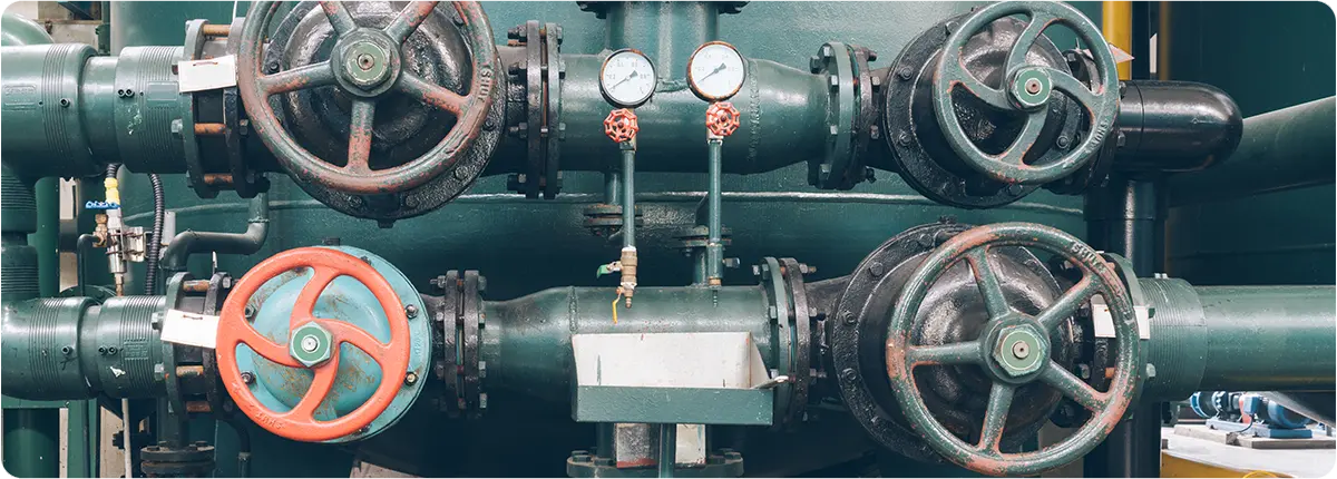
Natural gas pressure reduction stations (PRS) are critical facilities that reduce the high-pressure gas delivered through transmission pipelines to safe levels for city networks and industrial plants. However, these operations involve significant energy consumption—mainly from heating systems, regulators, compressors, and control equipment. Rising energy costs and global commitments to reduce carbon emissions make energy efficiency and optimization strategies essential for modern PRS facilities.

Energy Efficiency and Optimization Methods in Natural Gas Pressure Reduction Stations


SOURCES OF ENERGY CONSUMPTION

Regulators and Heating Systems
When natural gas pressure is reduced, it experiences cooling due to the Joule–Thomson effect. To prevent condensation and freezing in downstream pipelines, gas heaters are used. These heating systems are often the largest energy consumers in PRS.

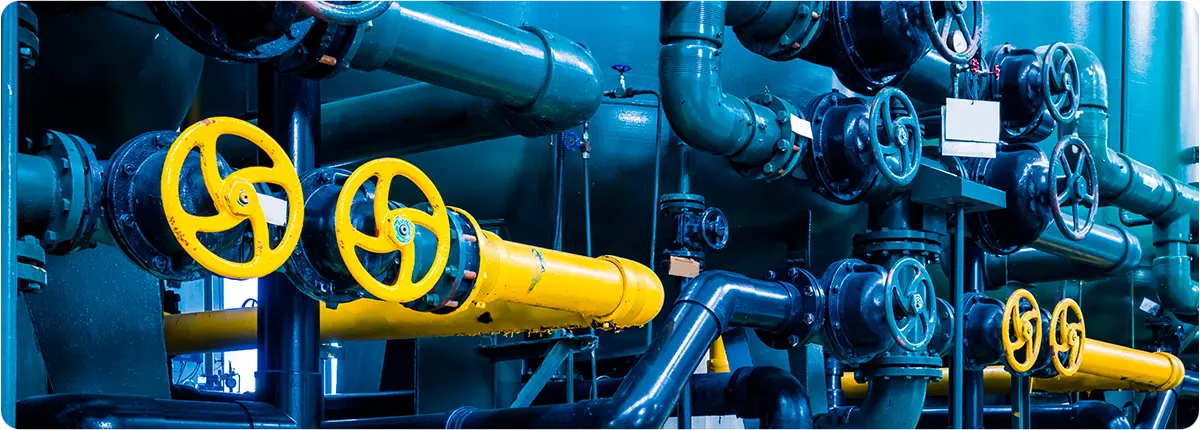
Compressors and Pumps
Some stations employ pumps or compressors to maintain pressure balance or direct gas toward measurement systems. These units significantly contribute to electrical energy consumption.

SCADA and Automation Systems
Although their share is smaller, SCADA servers, sensors, and controllers add to the station’s continuous energy load.

METHODS FOR IMPROVING ENERGY EFFICIENCY

Waste Heat Recovery Systems
By recovering heat from exhaust gases or flue gases, PRS can reduce the energy demand of heating systems. Heat recovery exchangers are increasingly being adopted to improve efficiency.

High-Efficiency Heaters
• Condensing boilers and high-performance heat exchangers offer up to 15–20% higher efficiency compared to conventional units.
• In some European PRS facilities, heat exchanger-based systems have replaced electric heaters, cutting costs and emissions.

Power Generation from Pressure Energy (Turboexpanders)
As natural gas expands from high to low pressure, it carries significant potential energy, which can be harnessed using turboexpanders.
• Benefit: Electricity production for station self-consumption or supply to the grid.
• Capacity: Installations can generate 10–20 MW of power, depending on flow and pressure conditions.

Preventing Gas Leaks
Even minor leaks from valves, seals, or joints cause substantial energy losses over time. Leak flow rates can be calculated using the orifice equation:
Q = Cd · A · √(2 · ΔP / ρ)
Routine tightness testing and predictive maintenance help eliminate such inefficiencies.

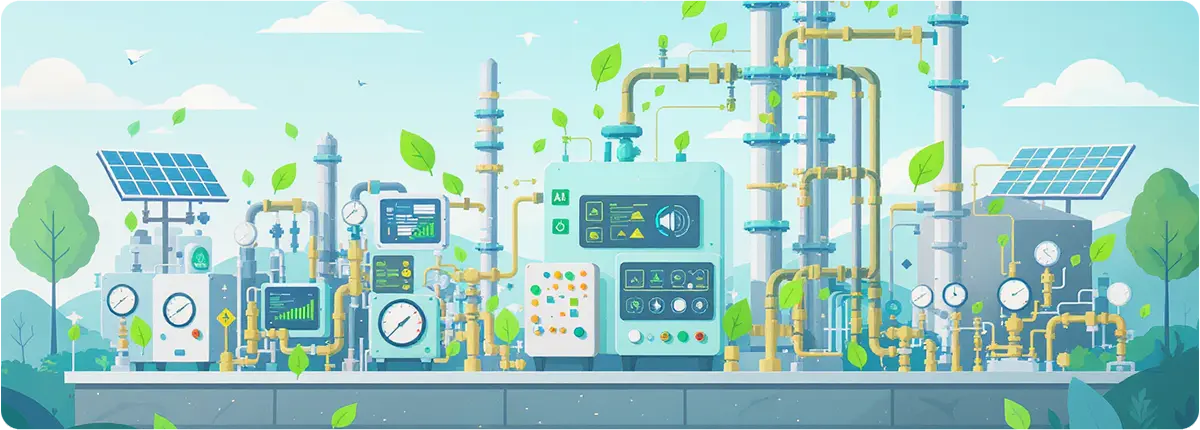
Smart Control Algorithms
• By integrating AI-driven optimization into SCADA systems, PRS facilities can minimize unnecessary heating and energy losses.
• Example: Adjusting regulator valve operation in gradual steps prevents sudden cooling, thereby reducing heater load.

ENGINEERING CALCULATIONS

Energy Released During Pressure Reduction
W = ṁ · R · T · ln(Pin / Pout)
• ṁ: Mass flow rate (kg/s)
• R: Gas constant (J/kg·K)
• T: Absolute temperature (K)
• Pin, Pout: Inlet and outlet pressure (Pa)
This formula is commonly used to estimate the electrical generation potential of turboexpander systems.

Heat Consumption for Gas Reheating
Q = ṁ · Cp · ΔT
• Cp: Specific heat capacity of gas
• ΔT: Required temperature increase

REAL-WORLD APPLICATIONS

Turkey: BOTAŞ city gate stations are implementing condensing boiler systems to lower heating demand.
Europe (Italy, Germany): Turboexpanders are installed in several PRS to generate millions of kWh annually from pressure energy.
Japan: AI-based SCADA systems have enabled 15–20% reductions in energy use in PRS operations.

CONCLUSION

Energy efficiency in natural gas pressure reduction stations is both an economic opportunity and an environmental necessity. Strategies such as:
• Efficient valves and heaters
• Heat recovery systems
• Turboexpander-based power generation
• Leak prevention and smart automation
can deliver up to 20% energy savings.
In the future, the integration of artificial intelligence and digital twin technology is expected to push energy optimization in PRS even further, ensuring both cost savings and environmental benefits.

Natural gas is transported through transmission pipelines at high pressures, typically between 40–70 bar, before it reaches city networks and industrial facilities. To ensure safe and efficient delivery, the pressure must be reduced and controlled. This is the responsibility of Pressure Reduction Stations (PRS), which play a vital role in natural gas infrastructure.

In recent decades, PRS operations have increasingly relied on automation technologies and advanced safety systems, ensuring reliability, efficiency, and protection for both people and the environment.

Valves Used in Pressure Reducing

THE ROLE OF AUTOMATION SYSTEMS

SCADA Integration

  • SCADA (Supervisory Control and Data Acquisition) platforms monitor key parameters such as pressure, flow, and temperature in real time.
  • Operators can remotely open and close valves, adjust regulator settings, and respond instantly to emergencies.

Sensors and Measurement Technologies

  • Pressure sensors: Detect sudden downstream fluctuations.
  • Flow meters: Measure consumption and assist in leak detection.
  • Temperature sensors: Track thermodynamic properties of gas.

Automated Valve Control

  • Critical PRS facilities employ pneumatically actuated ball valves for rapid response.
  • In emergencies, these valves close automatically, triggered by SCADA commands or sensor signals, ensuring fast isolation of the pipeline.

SAFETY SYSTEMS

Pressure Safety Valves (PSVs)

  • Protect against unexpected overpressure conditions.
  • Designed in accordance with API 520/521 standards.

Dual Regulation + By-Pass Design

  • If one regulator fails, the secondary regulator maintains supply.
  • By-pass valves ensure continuous flow during maintenance operations.

Gas Leak Detectors

  • Detect even minor leaks within the station.
  • Integrated into SCADA systems for early warnings and rapid intervention.

Fire and Explosion Sensors

  • Flame and heat detectors enhance safety monitoring.
  • In high-risk events, automatic fire suppression systems are activated.

ENGINEERING CALCULATIONS

Pressure Drop Calculation

ΔP = Pin − Pout

  • Pin: Inlet pressure (bar)
  • Pout: Outlet pressure (bar)

Example: If inlet pressure is 70 bar and outlet pressure is reduced to 19 bar:
ΔP = 70 − 19 = 51 bar

PSV Set Pressure

Safety valve set pressures are typically 110–120% of outlet pressure.

  • For 19 bar outlet pressure, PSV set pressure ≈ 21–22 bar.

SCADA Trend Analysis

  • Collected sensor data is displayed as trend graphs.
  • These graphs help verify regulator stability and detect anomalies in real time.

REAL-WORLD APPLICATIONS

  • Turkey (BOTAŞ City Gate Stations): Equipped with dual regulators, safety valves, and SCADA-based automation as a standard.
  • Germany (Ruhr Region): Uses redundant regulator systems with by-pass valves for 100% backup reliability.
  • Japan: Seismic sensors are integrated into PRS to automatically shut down gas flow during earthquakes.

CONCLUSION

Automation and safety systems in natural gas pressure reduction stations are no longer optional—they are a necessity. With SCADA integration, advanced sensors, safety valves, and intelligent control systems, PRS facilities achieve:

  • Higher operational efficiency
  • Rapid response to emergencies
  • Enhanced protection of people and the environment

Looking ahead, predictive maintenance powered by artificial intelligence and smarter sensor technologies will further improve the safety and reliability of natural gas infrastructure worldwide.

In high-pressure transmission pipelines, natural gas typically flows at 40–70 bar. However, city networks and industrial facilities require the gas at much lower pressures, usually between 1–20 bar. This adjustment is achieved in pressure reduction stations (PRS). Within these stations, valves play a critical role, not only in reducing pressure but also in ensuring operational safety, efficiency, and continuity.

Valves Used in Pressure Reducing

KEY TYPES OF VALVES IN PRESSURE REDUCTION STATIONS

Pressure Reducing Valves (PRVs)

  • The primary element of PRS, designed to reduce high inlet pressure to a stable and safe outlet pressure.
  • Features:
    • Precise control of downstream pressure
    • Noise and cavitation reduction options
    • Compatible with automation and control systems
  • Standards: EN 334, ISO 23555

By-Pass Valves

  • Provide redundancy in case of regulator failure or during maintenance.
  • Example: Critical installations often employ dual regulators plus a by-pass line to guarantee uninterrupted supply.

Blowdown / Drain Valves

  • Used to depressurize or empty sections of the pipeline.
  • Function: Ensures maintenance safety by isolating sections under pressure.

Safety and Relief Valves

  • Protect the system against unexpected overpressure conditions.
  • Working principle: Opens automatically at a preset pressure to release excess gas.

Control Valves

  • Integrated into SCADA and PLC systems for continuous monitoring.
  • Adjust flow, pressure, and temperature parameters dynamically.
  • Essential in industrial city gate stations with high consumption levels.

VALVE SELECTION CONSIDERATIONS

Flow Range and Capacity

Valves must cover both minimum and maximum consumption scenarios.

  • Example: For a PRS with a design flow of 5,000 Sm³/h, the pressure reducing valve should reliably handle flows between 2,000–7,000 Sm³/h.

Pressure Drop (ΔP)

Pressure reduction is the core task of PRS valves.
ΔP = Pin − Pout

  • Pin: Inlet pressure (bar)
  • Pout: Outlet pressure (bar)

Engineering Note: Rapid fluctuations in outlet pressure can trigger cavitation and noise problems.

Control Characteristics

  • Linear: Flow increases proportionally with valve opening.
  • Equal Percentage: Provides stable control at low openings and rapid flow increase at higher openings.
  • Quick Opening: Best suited for emergency shutoff or rapid actuation.

Cavitation and Noise Control

  • High-pressure drops can cause cavitation inside the valve body.
  • Solution: Multi-stage pressure-reducing valves or silencers.

Actuator Type

  • Pneumatic Actuators: Fast response, most common in PRS.
  • Electric Actuators: Strong integration with SCADA but slower response.
  • Hydraulic Actuators: Used in extra-large valve sizes.

SAFETY AND STANDARDS

  • EN 334 – Gas pressure regulators
  • ISO 23555 – Industrial gas pressure regulation
  • PED (Pressure Equipment Directive) – EU pressure equipment directive
  • ASME – Pressure ratings and design standards

REAL-WORLD APPLICATIONS

  • Istanbul City Gate Stations (Turkey): High-capacity PRVs reduce gas pressure from 70 bar to 19 bar for city distribution.
  • Ruhr Region (Germany): Dual regulators with by-pass valves provide 100% redundancy for enhanced reliability.
  • Japan: Multi-stage noise-reducing valves are installed in urban PRS located near residential areas.

CONCLUSION

Valves in pressure reduction stations are fundamental to safe, efficient, and uninterrupted natural gas distribution. Selection must consider flow ranges, pressure drops, cavitation risk, and automation requirements. Modern PRS increasingly rely on SCADA integration, advanced regulators, and multi-stage valve designs to ensure both operational efficiency and safety. Choosing the right valve technology is not just a matter of performance—it is a cornerstone of reliable and sustainable gas supply.

Natural gas plays a vital role in meeting the world’s energy demand, and its safe transmission depends heavily on the performance of valves installed in pipelines. Valves regulate flow, control pressure, isolate sections of the pipeline, and provide emergency shutdown capabilities. Choosing the wrong type of valve not only reduces efficiency but can also lead to severe safety risks.

This article examines the types of valves used in natural gas pipelines, their features, material and standard requirements, and key factors engineers must consider when selecting them.

Natural Gas Pipelines

MAIN VALVE TYPES IN NATURAL GAS PIPELINES

Ball Valves

  • The most widely used valves in natural gas systems.
  • Advantages: Full-bore design minimizes pressure drop. Operated with a quarter-turn (90°), making them ideal for emergency shutoff.
  • Applications: Commonly used in long-distance transmission pipelines and city gate stations.

Gate Valves

  • Preferred in large-diameter transmission lines.
  • Advantages: Minimal flow resistance when fully open.
  • Disadvantages: Slower to operate compared to ball valves.
  • Example: Frequently installed in 36” and larger pipeline sections.

Butterfly Valves

  • Compact and cost-effective solutions for large-diameter lines.
  • Advantages: Lightweight, simple construction, and economical.
  • Applications: More common in distribution networks operating at medium pressure.

Control Valves

  • Designed to regulate flow rate and pressure.
  • Features: Can be integrated into SCADA and automation systems.
  • Example: LNG terminals rely on control valves for continuous adjustment of gas flow.

Safety and Relief Valves

  • Protect pipelines from overpressure events.
  • Operation: Open at a preset pressure, venting gas to the atmosphere.
  • Standard: Designed according to API 520/521.

Check Valves

  • Prevent reverse flow, protecting compressors and downstream equipment.
  • Example: A standard component in compressor stations.

MATERIAL SELECTION AND STANDARDS

  • Common Materials:
    • Carbon steel (ASTM A105, A216 WCB)
    • Low-temperature steels (ASTM A350 LF2)
    • Stainless steels (AISI 304, 316) for corrosive environments
  • Relevant Standards:
    • API 6D – Pipeline valves
    • ASME B16.34 – Pressure-temperature ratings
    • ISO 14313 – International pipeline valve standard

KEY SELECTION CRITERIA

Pressure Class

Valves are designed according to ANSI classes ranging from 150 to 2500.
Example: A 70-bar transmission pipeline typically requires a Class 600 valve.

Flow Coefficient (Cv)

The capacity of a valve is defined by its flow coefficient:

Q = Cv · √(ΔP / G)

  • Q: Flow rate (m³/h)
  • ΔP: Pressure drop (bar)
  • G: Specific gravity of gas

Temperature and Operating Conditions

  • Natural gas is usually transported between -20 °C and +60 °C.
  • Valve seals and body materials must be compatible with this range.

Automation and Remote Control

  • Critical stations require actuated valves (electric, pneumatic, or hydraulic).
  • Example: City gate stations often use pneumatically actuated ball valves integrated into SCADA.

Safety and Maintainability

  • Valves with Double Block & Bleed (DBB) design improve maintenance safety.
  • They also allow testing of pipeline segments under pressure.

REAL-WORLD APPLICATIONS

  • TANAP Project (Turkey): The 1,850 km Trans-Anatolian Natural Gas Pipeline relies on API 6D ball valves for high-pressure transmission.
  • European Distribution Networks: Medium-pressure networks frequently use butterfly and control valves.
  • Compressor Stations: Check valves are indispensable to prevent backflow damage.

CONCLUSION

Valves in natural gas pipelines are essential for safety, efficiency, and operational continuity. From ball and gate valves to butterfly, control, and relief valves, the selection depends on pipe diameter, pressure class, flow capacity, and automation requirements.

Improper valve selection can result in high operational costs or serious safety hazards. Therefore, engineers must rely on API, ASME, and ISO standards, ensuring each valve is designed and chosen for the specific conditions of the pipeline.