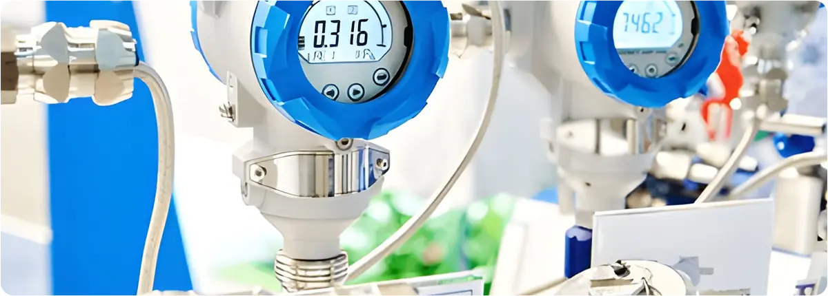
Smart pressure transmitters represent the evolution of traditional pressure measurement devices, integrating advanced sensors, microprocessors, and digital communication protocols. They not only measure pressure but also provide self-diagnostics, remote monitoring, and seamless integration with advanced control systems, enhancing process safety, energy efficiency, and reducing maintenance costs.

Pressure Transmitters

WORKING PRINCIPLE

Smart pressure transmitters operate by converting applied pressure into an electrical signal through a diaphragm and sensing element. The most common sensor technologies include:

  • Piezoresistive sensors
  • Capacitive sensors
  • Piezoelectric sensors
  • Strain gauge elements

The analog signals are digitized by microprocessors, processed, filtered, and then transmitted to control systems.

Basic equation:
P = F / A
P: Pressure (Pa)
F: Force (N)
A: Area (m²)

STRUCTURAL FEATURES

  • High-quality diaphragm materials (stainless steel, tantalum, monel, ceramic)
  • Microprocessor-based electronics
  • Output protocols: 4-20 mA, HART, Profibus, Fieldbus, Modbus, WirelessHART
  • Protection ratings: IP65 – IP68
  • Explosion-proof models (ATEX, IECEx)

SMART FUNCTIONS

  • Self-diagnosis for malfunction detection
  • Predictive maintenance
  • Remote monitoring and calibration
  • Data logging and trend analysis
  • Automatic zero/span adjustment
  • Integration with SCADA/DCS systems

SELECTION CRITERIA

  • Measurement range and accuracy
  • Process environment (temperature, pressure, chemical compatibility)
  • Communication protocols
  • Certifications (ATEX, SIL, CE)
  • Mounting options and mechanical strength

ADVANTAGES AND LIMITATIONS

Advantages:

  • High accuracy and long-term stability
  • Remote access and data analytics
  • Reduced maintenance costs
  • Ready for Industry 4.0 and IIoT integration

Limitations:

  • Higher initial cost
  • Requires specialized configuration
  • Cybersecurity risks

APPLICATION AREAS

  • Oil and gas industry (pipelines, refineries)
  • Chemical plants (reactor pressure monitoring)
  • Power plants (boiler and turbine monitoring)
  • Food and pharmaceutical industry (hygienic processes)
  • Water and wastewater treatment facilities

STANDARDS AND CALIBRATION

  • IEC 61508 (SIL certification)
  • NAMUR NE107 (diagnostic status)
  • ISO/IEC 17025 (calibration)
  • Hart and Fieldbus compliance standards

CONCLUSION

Smart pressure transmitters are essential devices for modern industrial automation, combining safety, efficiency, and digitalization. When properly selected and applied, they offer significant long-term benefits to industries.

Pressure transmitters are essential instruments used in industrial facilities to enhance process safety and efficiency. They convert pressure into standardized electrical signals (e.g., 4-20 mA) and transmit them to control systems. They are widely applied in oil and gas, chemical, energy, food, pharmaceutical, water, and wastewater industries.

WORKING PRINCIPLE

The operating principle of a pressure transmitter is based on the deformation or electrical variation caused by applied pressure. The main measurement technologies include:

  • Strain gauge: measures resistance changes due to diaphragm deformation.
  • Piezoresistive sensors: rely on resistance changes in semiconductor materials.
  • Capacitive sensors: measure capacitance changes as the diaphragm moves.
  • Piezoelectric sensors: generate voltage proportional to applied pressure.

Basic equation:
P = F / A
P: Pressure (Pa)
F: Force (N)
A: Area (m²).

This principle ensures accurate and repeatable conversion of applied pressure into electrical signals.

STRUCTURAL FEATURES

  • Housing: stainless steel, aluminum, or special alloys
  • Diaphragm: stainless steel, monel, tantalum, ceramic
  • Electronics: analog/digital signal processing
  • Output signals: 4-20 mA, HART, Fieldbus, Profibus
  • Protection ratings: IP65 – IP68
  • Explosion-proof models (ATEX, IECEx)

TYPES OF PRESSURE TRANSMITTERS

  • Gauge pressure transmitters: measure pressure relative to atmospheric pressure.
  • Absolute pressure transmitters: measure relative to a vacuum reference.
  • Differential pressure transmitters: measure pressure difference between two points, commonly used in flow measurement.
  • Multivariable transmitters: measure pressure, temperature, and flow simultaneously.

SELECTION CRITERIA

Key factors when selecting a pressure transmitter include:

  • Measurement range (rangeability)
  • Accuracy class
  • Process temperature and pressure
  • Material compatibility
  • Output communication protocols
  • Certifications (ATEX, SIL, CE)
  • Mounting type (flanged, threaded, manifold connection)

ADVANTAGES AND LIMITATIONS

Advantages:

  • High accuracy and reliability
  • Wide measurement range
  • Digital communication integration
  • Long-term stability

Limitations:

  • Regular calibration required
  • Special diaphragms needed for abrasive or high-temperature media
  • Can be costly depending on specifications

APPLICATION AREAS

  • Pressure monitoring in oil and gas pipelines
  • Reactor pressure in chemical plants
  • Boiler pressure in power plants
  • Pump pressure in water and wastewater plants
  • Hygienic pressure measurement in food and pharmaceutical industries

STANDARDS AND CALIBRATION

  • IEC 61508 (SIL – Safety Integrity Level)
  • NAMUR NE43 (fault signal handling)
  • ISO/IEC 17025 (calibration)
  • OIML R 117 (measurement standards)

Regular calibration is essential for maintaining reliable measurement over time.

CONCLUSION

Pressure transmitters are indispensable devices for industrial automation and process safety. When properly selected, they enhance both safety and efficiency in industrial operations.