Description
Application
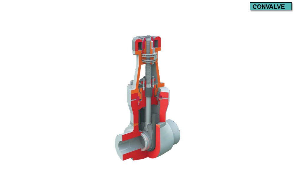
Shut-off valve designed for water, water steam and other op- eration fluids used in power engineering and chemical industry according to selection of material of valve, for normal, tropical, explosive, seismic environments.
Technical description
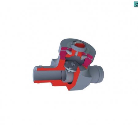
The body of the valve is a die or free forged piece, cast or welded yoke. The seats are pressed into the body and welded by seal weld. Sealing surfaces of seats and wedge are welded by hard welding alloy. Gland packing of stem and sealing ring of pressure sealed cover are of expanded graphite.
The gate valves are designed for full pressure head and no bypasses need to be installed. When bypass is required, one to three valves and a T-piece are fitted for bypass piping. Further they can be fitted by protection of central part of the body.

Gland with permanently pushing spring
Upon request the type of gland with permanently pushing spring (so called Live Loading System) may be delivered.
This design solution is used in cases, when operational condi- tions do not allow frequent checks of the valve condition or the nature of operation makes regular maintenance of the gland im- possible.
Operation
The gate valve is operated by hand wheel, electric actuator (also for seismic requirements), via spur or bevel gear and with di- rect remote control. Hand wheel gate valves may be equipped by locking mechanism.

Protection of inner part of the gate valve body
In some piping systems a situation may arise, when after the system shut down and following cooling, certain volume of wa- ter remains in the central part of the gate valve; i.e. in the space above the wedge.
If such gate valve is heated in a closed state through bypass later, due to rising temperature a simple physical effect occurs, increase of pressure between wedge boards and in the space above it (in so called chamber).
Providing a requisite of potential situations arising during valve operation, it is necessary to state requirements for delivery of gate valve with protection of the inner part of the body in the order.

 Design solution of the protection
- Drilling through one of the wedge board and hence con- necting central part with intake hub. It is the simplest solu- tion. Applicable only as a one-way valve. Flow direction must be indicated.
- Connecting bypass with central part, rather simple and ef- fective solution. Application with all bypasses consisting of at least two valves, between which there is the bypass. These are all gate valves of diameter DN 200 and larger. One valve has always to be opened according to the flow.
- Relief valve located at the end of pipe leading out of the gate valve chamber. It is more expensive, although absolutely universal solution, which could be used on all gate valves for all operation parameters. Setting of relief pressure must be specified in the order.
Testing
The gate valves are pressure tested with water (upon client request even by steam) for strength, impermeability, operation ability and for tightness according to operating parameters and material of the body. Minimum strength testing pressure is 1,5 fold of PN. The strength welds are tested by X-ray scan- ning.
Installation
The gate valves are installed in any position regardless of the di- rection of operation fluid flowing. Larger diameter gate valves are recommended to be installed in horizontal piping, with verti- cal stem, with control up.
Connection
Butt-welded and flanged as per CSN, DIN, ANSI, GOST standards.
The gate valves may also be delivered with electric actuators by manufacturers ZPA Pečky, Regada, AUMA, Rotork, Schiebel and others.
