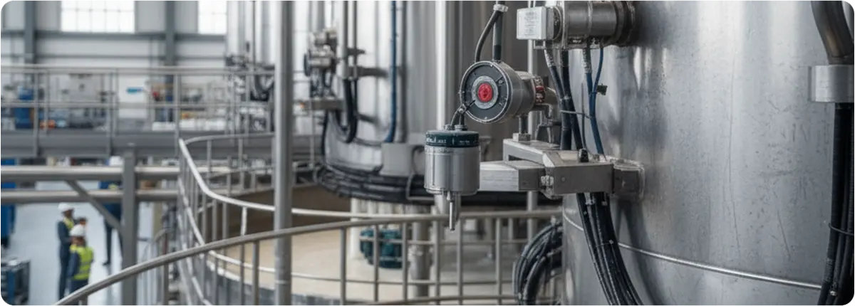
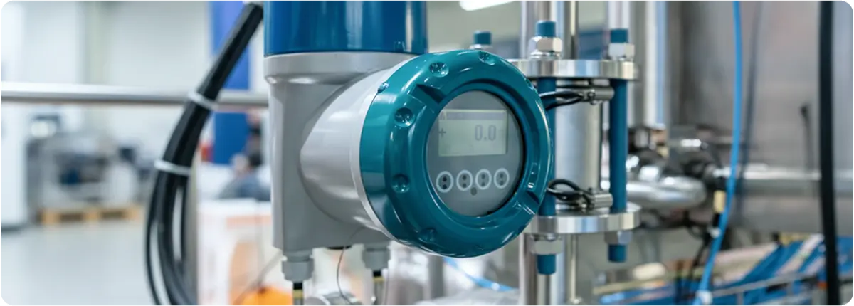
Posts

In industrial facilities, monitoring the level of liquids, solids, or semi-solids in tanks and pipelines is essential for process safety and efficiency. Level switches are widely used to prevent overflow, protect pumps from dry running, and maintain safe operation. Unlike continuous level transmitters, level switches are point-level devices that generate on/off signals at predefined levels.

Level Measurement Systems and Sensors

WORKING PRINCIPLE

A level switch detects when a medium reaches a set height and provides a switching signal. This signal can activate pumps, valves, alarms, or shutdown systems.

Types include:

  • Float switches
  • Capacitive switches
  • Ultrasonic switches
  • Thermal switches
  • Tuning fork switches

TYPES OF LEVEL SWITCHES

  1. Float type
  2. Magnetic type
  3. Capacitive type
  4. Ultrasonic type
  5. Tuning fork type
  6. Thermal type

APPLICATION AREAS

  • Water and wastewater treatment
  • Food and beverage
  • Chemical and petrochemical
  • Energy and boiler systems
  • Bulk material silos

ADVANTAGES

  • Reliable and simple operation
  • Wide application range
  • Prevention of critical incidents
  • Low maintenance

LIMITATIONS

  • Only point-level detection
  • May be affected by foam or buildup
  • Require special designs for extreme conditions

TECHNICAL SELECTION CRITERIA

  1. Process media properties
  2. Temperature and pressure
  3. Sanitary requirements
  4. Hazardous environment certifications
  5. Mounting method

ENGINEERING NOTE AND EXAMPLE

In a tank with a high level set at H = 2.5 m, a float level switch activates at this point:

  • Pump stops
  • Alarm is triggered
  • Overflow risk is eliminated

RECOMMENDED LEVEL SWITCHES BY APPLICATION

Application Recommended Type Advantage
Water storage Float Simple and cost-effective
Chemical tanks Capacitive / Ultrasonic Corrosion-resistant, contactless
Steam boilers Thermal Reliable low-level detection
Powder silos Tuning fork Not affected by dust
Food processing tanks Hygienic capacitive CIP/SIP compatible

CONCLUSION

Level switches are essential point-level detection devices that enhance process safety and reliability. With proper selection and installation, they deliver dependable performance in diverse industries.

In industrial plants, accurate level measurement of liquids, solids, and semi-solids is vital for process safety, quality control, and operational continuity. Among the available technologies, capacitive level transmitters stand out due to their high accuracy, robust design, and broad range of applications. These devices are widely used in industries such as food, chemicals, petrochemicals, cement, pharmaceuticals, and energy.

Capacitive Level Transmitters

WORKING PRINCIPLE

Capacitive level transmitters operate on the principle of capacitance change. Essentially, the system functions as follows:

Formula: C = ε · A / d

  • C: Capacitance (Farads)
  • ε: Dielectric constant of the medium
  • A: Electrode surface area
  • d: Distance between electrodes

A probe (electrode) inserted into a tank, together with the tank wall, forms a capacitor. As the tank fills, the dielectric constant changes depending on the medium:

  • Air → low dielectric (ε ≈ 1)
  • Water → high dielectric (ε ≈ 80)

As the fill level increases, the capacitance value changes, and the transmitter converts this variation into a level measurement.

EXAMPLE CALCULATION

For a 2 m probe with an electrode area of 50 cm² and a distance of 5 mm:

  • When filled with air: C_air ≈ 8.85 pF
  • When filled with water: C_water ≈ 708 pF

This large difference enables highly accurate level measurement.

APPLICATIONS

  • Liquids: water, acids, solvents, oils, paints
  • Solids: flour, sugar, cement, plastic granules, coal dust
  • Special media: foamy liquids, sticky substances, high-pressure or high-temperature tanks

ADVANTAGES

  • Wide applicability for liquids and solids
  • Resistant to pressure and temperature variations
  • High accuracy and repeatability
  • Corrosion-resistant coatings for aggressive chemicals
  • Easy calibration and setup

DISADVANTAGES

  • Accuracy depends on dielectric constant
  • Build-up of sticky materials may cause errors
  • Improper grounding in metallic tanks may cause faulty readings

TECHNICAL SELECTION CRITERIA

  • Dielectric constant: materials with ε < 2 require high-sensitivity models
  • Temperature and pressure: ensure compatibility with process conditions
  • Tank structure: choose appropriate probe for plastic, metal, or concrete tanks
  • Explosive environments: use ATEX or IECEx certified models

CALIBRATION AND MAINTENANCE NOTES

  • Calibrate at empty and full tank conditions
  • Regularly clean probes from dust or deposits
  • Replace damaged insulation (Teflon or ceramic)
  • Ensure proper grounding to prevent measurement errors

ENGINEERING NOTES

  • Accuracy: up to ±0.5% FS
  • Output signals: 4–20 mA, HART, Profibus, Modbus
  • Measurement range: 0.2 m – 20 m
  • Process connections: flanged, threaded, or clamped

RECOMMENDED DESIGNS BY APPLICATION

Application Dielectric Constant Recommended Design Notes
Water tank ≈ 80 Standard probe High accuracy
Oil tank 2 – 5 Insulated probe Requires calibration due to low ε
Cement silo 3 – 7 Rod/rope probe Regular cleaning required
Acid tank 50 – 70 PTFE-coated probe High corrosion resistance

CONCLUSION

Capacitive level transmitters provide a reliable, economical, and precise measurement solution. Thanks to their dielectric-based principle, they can be used effectively in both liquids and solids. With proper selection, calibration, and maintenance, they ensure long-lasting and accurate measurements in various industries.

Pressure switches are control devices that open or close an electrical contact when a preset pressure level is reached. Due to their simplicity, they are widely used in both safety and automation applications. From pump protection to industrial process safety, they play a critical role in ensuring reliability.

WORKING PRINCIPLE

When pressure is applied on the diaphragm, it causes mechanical movement that actuates an electrical mechanism. This mechanism results in the opening or closing of contacts. The fundamental principle is based on the relationship between pressure, force, and area:

Formula: P = F / A

Where P: Pressure (Pa), F: Force (N), A: Area (m²).

STRUCTURAL FEATURES

  • Body materials: stainless steel, brass, plastic
  • Diaphragm materials: NBR, EPDM, stainless steel
  • Contact types: NO (normally open), NC (normally closed), SPDT
  • Electrical connection options and IP protection classes

TYPES

  • Mechanical pressure switches
  • Electronic/digital pressure switches (with display, microprocessor controlled)
  • Vacuum switches
  • Differential pressure switches

SELECTION CRITERIA

  • Measurement range (bar, psi)
  • Maximum operating pressure
  • Contact rating (AC/DC values)
  • Process connection (threaded, flanged)
  • Environmental conditions (temperature, vibration, humidity, ATEX certification)

ADVANTAGES AND LIMITATIONS

Advantages:

  • Simple and reliable operation
  • No energy required for mechanical types
  • Cost-effective
  • Wide application range

Limitations:

  • Lower accuracy in mechanical types
  • Wear and calibration needs
  • Higher cost for electronic models

APPLICATION AREAS

  • Pump and compressor protection
  • Pressure safety in hydraulic and pneumatic systems
  • Boilers and steam systems
  • Water treatment plants
  • HVAC and automotive applications

STANDARDS

  • IEC 60947 (low-voltage switchgear)
  • EN 60947-5-1 (switches)
  • ATEX certifications (for explosive atmospheres)

CONCLUSION

Pressure switches are cost-effective, reliable, and widely used control devices in critical applications. When properly selected, they provide indispensable protection for equipment and ensure process safety.

Flow switches are devices used to detect the presence, absence, or threshold level of liquid or gas flow in pipelines. They play a vital role in process safety and equipment protection, especially in preventing pump dry-running, ensuring coolant circulation, and monitoring flow in fire suppression systems.

Flow Switches and Industrial Applications

WORKING PRINCIPLE

A flow switch operates when flow speed falls below or rises above a preset threshold. This triggers a contact mechanism that sends an alarm, warning, or shutdown signal.

Main types:

  • Mechanical (Paddle) Flow Switch
  • Magnetic Flow Switch (float with reed switch)
  • Electronic Flow Switch (thermal or differential pressure-based)

TECHNICAL FEATURES AND EQUATIONS

The threshold flow can be estimated using the equation:

Q = A · v

Where Q is flow rate (m³/s), A is cross-sectional area (m²), v is flow velocity (m/s).

Important parameters include pressure and temperature resistance, hysteresis values, and contact type (NO, NC).

ADVANTAGES AND LIMITATIONS

Advantages:

  • Ensures process safety
  • Protects pumps and compressors from dry running
  • Easy integration into automation systems

Limitations:

  • Does not provide precise flow measurement
  • Sensitivity can be affected by viscosity and particles
  • Some models require frequent maintenance

APPLICATION AREAS

  • Pump protection systems
  • Cooling water circuits
  • Fire suppression (sprinkler) systems
  • Chemical, food, and pharmaceutical industries for process safety

STANDARDS AND SAFETY

  • IEC and EN: Electrical safety and control standards
  • NFPA: Fire suppression systems
  • ISO 9001: Quality assurance and calibration practices

CONCLUSION

Despite their simple design, flow switches are critical for process safety in industrial plants. Modern versions with digital outputs can be integrated into SCADA and automation systems, offering enhanced monitoring and protection.

Pressure measurement plays a vital role in industrial processes by ensuring safety, product quality, and energy efficiency. Inaccurate pressure readings can lead to equipment failures, production losses, and safety hazards. Therefore, the selection and use of the right pressure measurement systems are essential.

Pressure Measurement Systems and Transducers

PRINCIPLES OF PRESSURE MEASUREMENT

Pressure is defined as the force exerted per unit area:

P = F / A

Where P is pressure (Pa), F is force (N), and A is surface area (m²).

Types of pressure:

  • Absolute Pressure: Measured relative to a perfect vacuum.
  • Gauge Pressure: Measured relative to atmospheric pressure.
  • Differential Pressure: The difference between two pressure points.

TYPES OF PRESSURE SENSORS

  • Bourdon Tubes: Mechanical indicators, cost-effective but limited in precision.
  • Differential Pressure Transducers: Widely used for flow measurement and filter monitoring.
  • Piezoelectric Sensors: Provide high sensitivity for dynamic pressure changes.
  • Capacitive Pressure Sensors: Offer high accuracy and long-term stability.
  • Strain Gauge Sensors: Measure pressure through changes in electrical resistance.

FUNDAMENTAL EQUATIONS AND MEASUREMENT EXAMPLES

Hydrostatic pressure formula:

P = ρ · g · h

Where ρ is fluid density (kg/m³), g is gravitational acceleration (9.81 m/s²), and h is fluid height (m).

Flow rate derived from differential pressure:

Q = C · √ΔP

Where Q is flow rate (m³/s), C is the flow coefficient, and ΔP is the pressure difference (Pa).

FACTORS AFFECTING MEASUREMENT ACCURACY

  • Temperature variations and thermal drift
  • Sensor calibration and accuracy
  • Vibrations in the pipeline
  • Installation conditions and environmental influences

STANDARDS AND CALIBRATION

  • ISO 5167: Standard for differential pressure measurement devices.
  • IEC 61298: Defines test methods for pressure transducers.
  • ISO 17025: Accreditation requirements for calibration laboratories.

APPLICATION AREAS

  • Reactor pressure control in chemical industries
  • Steam line monitoring in power plants
  • Pipeline pressure monitoring in oil and gas sectors
  • Process pressure management in the food and beverage industry

CONCLUSION

Pressure measurement systems are critical to ensuring safety and efficiency in industrial plants. By selecting the appropriate sensor, performing regular calibration, and ensuring proper maintenance, processes can be managed reliably and sustainably.

Level measurement is one of the most vital aspects of industrial processes. Accurate level control in storage tanks, silos, and pipelines is essential for production efficiency, process safety, and cost optimization.

Level Measurement Systems and Sensors

LEVEL MEASUREMENT METHODS

  • Mechanical Methods: Float systems and level indicators; simple but limited in accuracy.
  • Hydrostatic Method: Calculates liquid level from the pressure at the tank bottom using pressure sensors.
  • Ultrasonic Sensors: Perform non-contact measurements using sound waves. May be affected by foam and vapor.
  • Radar (Microwave) Sensors: Provide high accuracy and reliability, suitable for challenging process conditions.
  • Capacitive Sensors: Measure changes in dielectric constant, applicable for both liquids and solids.

BASIC PRINCIPLES AND FORMULAS

Hydrostatic level measurement formula: P = ρ · g · h

Where P is pressure (Pa), ρ is fluid density (kg/m³), g is gravitational acceleration (9.81 m/s²), and h is level height (m).

Capacitive level measurement formula: C = (ε · A) / d

Where C is capacitance (F), ε is dielectric constant, A is plate area, and d is distance between plates.

FACTORS AFFECTING MEASUREMENT ACCURACY

  • Variations in fluid density, temperature, and viscosity
  • Tank geometry and sensor installation position
  • Foam, vapor, and pressure fluctuations
  • Calibration and regular maintenance of sensors

STANDARDS AND CALIBRATION

  • IEC 60079: For explosion-proof level sensors in hazardous environments.
  • ISO 9001: Process validation and quality management standards.
  • ISO 17025: Accreditation for calibration laboratories.

APPLICATION AREAS

  • Monitoring tank and basin levels in water and wastewater treatment plants
  • Reactors and storage tanks in chemical industries
  • Liquid raw material monitoring in the food industry
  • Tank level management in oil and gas industries

CONCLUSION

Level measurement systems are critical for ensuring process safety and efficiency. Correct sensor selection, proper installation, and regular calibration allow industrial plants to operate reliably and sustainably.

Temperature is one of the most critical parameters in industrial processes. Incorrect temperature measurement can lead to reduced product quality, energy inefficiency, and even serious safety risks. For this reason, temperature measurement systems and sensors are integral parts of process control.

Temperature Measurement Methods and Sensors

PRINCIPLES OF TEMPERATURE MEASUREMENT

Temperature measurement is used to determine the energy state of fluids or solids. The fundamental formula is:

Q = m · c · ΔT

Where Q is heat energy (J), m is mass (kg), c is specific heat capacity (J/kgK), and ΔT is the temperature change (K).

Heat transfer mechanisms — conduction, convection, and radiation — must be considered when positioning temperature sensors.

TYPES OF TEMPERATURE SENSORS

• Thermocouples: Based on the Seebeck effect, suitable for a wide temperature range.
• RTDs (Resistance Temperature Detectors): Measure resistance changes, offering high accuracy.
• Thermistors: Provide very precise readings over a narrower temperature range.
• Infrared (IR) Sensors: Enable non-contact temperature measurement.
• Bimetal Thermometers: Simple mechanical devices operating on thermal expansion.

FACTORS AFFECTING MEASUREMENT ACCURACY

• Calibration of the sensor
• Immersion depth and sensor positioning
• Environmental conditions such as humidity, vibration, and electromagnetic interference
• Quality of insulation materials

If these factors are not considered, measurement errors may increase significantly.

STANDARDS AND CALIBRATION

• IEC 60751: International standard for RTD sensors.
• ASTM E230: Defines thermocouple classes and tolerances.
• ISO 17025: Accreditation standard for calibration laboratories.

APPLICATION AREAS

• Turbine and boiler temperature monitoring in power plants
• Reactor temperature measurement in chemical industries
• Pasteurization and cooking processes in the food industry
• Ambient temperature control in HVAC systems

CONCLUSION

Selecting the right sensor, performing regular calibration, and ensuring proper installation make temperature measurement systems indispensable for safety, efficiency, and product quality in industrial operations.

Flow measurement is one of the most critical parameters in industrial processes. The amount, velocity, and characteristics of a fluid directly affect product quality and system efficiency in industries such as power generation, water treatment, petrochemicals, and food production.

Flow Measurement Techniques

FLOW CONCEPT AND BASIC FORMULA

Flow (Q) is the volume of fluid passing through a cross-section per unit of time.

Formula:
Q = A · v

Where Q (m³/s) is the flow rate, A (m²) is the pipe cross-sectional area, and v (m/s) is the average velocity.

The Bernoulli principle, which describes the conservation of energy in a fluid, forms the basis of many flow measurement techniques.

MECHANICAL MEASUREMENT METHODS

• Orifice Plate: Based on pressure drop; a cost-effective but less accurate method.
• Venturi Tube: Provides higher accuracy with minimal pressure loss.
• Pitot Tube: Commonly used for velocity measurement.
These methods are defined under ISO 5167 standards.

MODERN FLOW MEASUREMENT TECHNOLOGIES

• Ultrasonic Flowmeter: Measures the effect of the fluid on sound waves; has no moving parts.
• Magnetic Flowmeter: Works on electromagnetic induction principle; suitable for conductive fluids.
• Mass Flowmeter (Coriolis): Directly measures mass flow with high accuracy, widely used in critical applications.

FACTORS AFFECTING MEASUREMENT ACCURACY

• Fluid viscosity
• Changes in temperature and density
• Turbulence within the pipeline
• Installation conditions and sensor placement

Ignoring these factors may result in significant measurement errors.

CALIBRATION AND STANDARDS

Regular calibration of flow measurement devices is necessary. ISO 5167 defines calibration methods for differential pressure devices such as orifice and Venturi tubes. Additionally, AGA reports (e.g., AGA3) are widely applied in natural gas flow measurement.

INDUSTRIAL APPLICATIONS

• Monitoring liquid and gas flows in petrochemical industries
• Steam and water flow control in power plants
• Inlet/outlet flow monitoring in water treatment plants
• Accurate liquid measurement in food industry processes

CONCLUSION

Accurate flow measurement is essential for process safety and efficiency. Proper device selection, compliance with standards, calibration, and correct installation conditions ensure reliable and sustainable operation of industrial facilities.

Pressure is one of the most critical parameters in industrial processes. Incorrect pressure measurement can lead to efficiency losses, safety hazards, and equipment damage. Therefore, pressure measurement systems and transducers form a cornerstone of measurement and control systems.

Pressure Measurement Systems and Transducers

PRESSURE CONCEPT AND BASIC FORMULA

Pressure is defined as the force applied perpendicular to a surface divided by the area of that surface.

Formula:
P = F / A

Where P is pressure (Pa), F is force (N), and A is surface area (m²).

PRESSURE MEASUREMENT DEVICES

• Manometers: Simple, low-cost solutions.
• Bourdon Tubes: Widely used mechanical devices.
• Strain Gauge Sensors: Measure pressure through changes in electrical resistance.
• Differential Pressure Transmitters: Also used in flow and level measurement.

TRANSDUCERS AND WORKING PRINCIPLE

Transducers are devices that convert pressure into electrical signals. The output is typically 4–20 mA or 0–10 V, enabling seamless integration with PLC and SCADA systems.

CALIBRATION AND ACCURACY

Pressure transmitters must be calibrated periodically. Calibration according to IEC 17025 ensures measurement accuracy and system reliability.

APPLICATION AREAS

• Steam pressure control in power plants
• Reactor pressure monitoring in petrochemical industries
• Membrane inlet pressure in water treatment plants
• Pressure monitoring in pasteurizers within the food industry

CONCLUSION

Pressure measurement systems are essential for process safety and efficiency. With proper device selection, regular calibration, and correct system integration, industrial facilities can achieve safe and sustainable operations.

In industrial facilities, efficiency, safety, and product quality depend heavily on the ability to measure, monitor, and control process variables. The systems designed for this purpose are known as measurement and control systems. From oil and gas refineries to food production plants, from power generation facilities to wastewater treatment, these systems form the backbone of industrial automation.

By implementing advanced measurement and control systems, plants achieve:
– Improved energy efficiency
– Standardized product quality
– Enhanced operational safety
– Reduced environmental impact.

Süreç İmalatında Öngörücü Bakım

THE IMPORTANCE OF MEASUREMENT AND CONTROL SYSTEMS

Every industrial process operates within a defined range of parameters. Deviations in pressure, temperature, flow, or level can result in energy waste, equipment damage, production losses, and even safety hazards. For this reason, measurement and control systems are often referred to as the ‘heart’ of industrial operations.

CORE COMPONENTS AND OPERATING PRINCIPLE

A measurement and control system typically consists of three main components:

Sensors / Transducers: Convert physical quantities into electrical signals (e.g., thermocouples, pressure transmitters, ultrasonic level sensors).
Controllers: Compare measured values with set points and generate control signals (e.g., PLCs, DCS, PID controllers).
Final Control Elements: Act directly on the process (e.g., control valves, actuators, motors).

Principle: The chain of Sensor → Controller → Final Control Element establishes the feedback loop that keeps the process stable.

CONTROL THEORY AND PID REGULATION

The most widely used algorithm in process industries is the PID controller, expressed by:

u(t) = Kp * e(t) + Ki ∫ e(t) dt + Kd * de(t)/dt

• e(t): Error signal (set point – measured value)
• Kp: Proportional gain (fast reaction)
• Ki: Integral gain (eliminates steady-state error)
• Kd: Derivative gain (responds to sudden changes)

Example: In a chemical reactor, poor PID tuning may cause runaway exothermic reactions, risking both product quality and plant safety.

KEY PROCESS VARIABLES

Pressure Measurement: Devices include Bourdon gauges, strain gauge sensors, and differential pressure transmitters.
Formula: P = F / A (Force per unit area)

Flow Measurement: Techniques include orifice plates, Venturi tubes, ultrasonic and magnetic flowmeters.
Fundamental relation: Q = A * v (Flow = cross-sectional area × velocity)

Temperature Measurement: Methods include thermocouples (Seebeck effect), RTDs (resistance change), and infrared sensors.
RTD relationship: R(T) = R0 * (1 + α * ΔT)

Level Measurement: Techniques include float, hydrostatic pressure, radar, and ultrasonic sensors.
Hydrostatic formula: h = P / (ρ * g)

INDUSTRIAL APPLICATIONS

Petrochemical Industry: Pressure and temperature control in distillation columns.
Power Plants: Boiler drum level and steam pressure regulation.
Food and Beverage: Pasteurization systems requiring precise temperature and flow control.
Water Treatment: Tank level monitoring and pH regulation in wastewater plants.

STANDARDS AND SAFETY REQUIREMENTS

Compliance with international standards is essential for reliability and safety:
– IEC 61511: Safety systems for process industries
– ISO 5167: Flow measurement standards
– ASME & API standards: Specific rules for oil and gas operations

CONCLUSION

Without measurement and control systems, modern industries could not operate safely or efficiently. Proper sensor selection, accurate controller tuning, and reliable final control elements are the foundation of industrial automation.

In the upcoming articles of this series, we will explore pressure, flow, temperature, and level measurement systems in greater technical depth.