Posts

Piston flowmeters are positive displacement flowmeters designed to provide high-accuracy measurement. They measure fluid volume through a reciprocating piston mechanism, making them ideal for low flow rates and high-viscosity fluids. Due to their reliability, they are widely used in chemical, pharmaceutical, food, oil, and automotive industries.

WORKING PRINCIPLE

In piston flowmeters, fluid enters a chamber where a piston moves back and forth. Each piston stroke displaces a fixed volume of fluid, which is then counted by mechanical or electronic sensors. The total volumetric flow rate is determined based on the number of cycles.

Basic equation:
Qv = n · Vc
Qv: volumetric flow rate (m³/s)
n: piston stroke frequency (Hz)
Vc: displaced volume per stroke (m³).

This principle ensures high accuracy, even at very low flow rates, and is less sensitive to pressure fluctuations.

STRUCTURAL FEATURES

  • Body materials: stainless steel, aluminum, cast iron
  • Measuring element: piston-cylinder mechanism
  • Output signals: mechanical register, magnetic pickup, pulse output
  • High-pressure resistance
  • Low pressure drop and high repeatability

ADVANTAGES AND LIMITATIONS

Advantages:

  • Very high accuracy (±0.1% – ±0.5%)
  • Effective for low flow measurements
  • Reliable for viscous fluids
  • Durable and long-lasting design

Limitations:

  • Maintenance required due to moving parts
  • Reduced lifespan with abrasive or particulate fluids
  • Limited use in large-diameter pipelines

APPLICATION AREAS

  • Solvent, resin, and polymer measurement in chemical industries
  • Precise dosing in pharmaceuticals
  • Measurement of syrup, honey, and oils in food industry
  • Oil and fuel measurement in automotive industry
  • Lubrication systems and hydraulic applications in energy sector

STANDARDS AND CALIBRATION

  • OIML R 117: International standard for liquid measuring devices
  • ISO/IEC 17025: Calibration laboratory accreditation
  • ATEX-certified models for explosive environments
  • Regular calibration is essential for maintaining accuracy over time

CONCLUSION

Piston flowmeters are highly reliable in low-flow and high-viscosity conditions. They play a critical role in industries requiring precise dosing and accurate volumetric flow measurement.
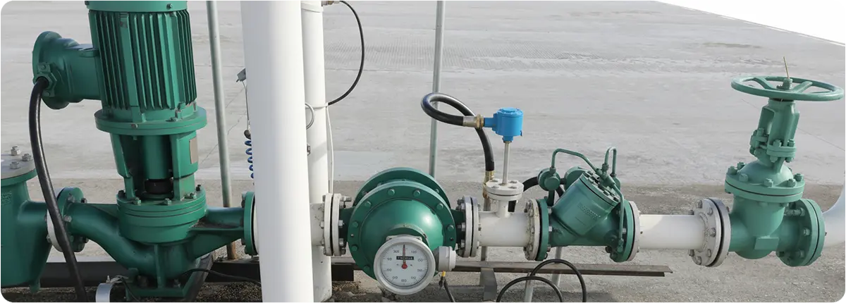
Helical rotor flowmeters are a special type of positive displacement flowmeter. They operate based on the principle of axial helical rotors being rotated by the fluid flow. Each rotation of the rotor represents a fixed and known volume, ensuring high accuracy and repeatability. They are widely used in petroleum, chemical, pharmaceutical, and food industries, particularly for measuring high-viscosity fluids.

Helical Rotor Flowmeters

WORKING PRINCIPLE

As the fluid passes through the meter, it causes the helical rotors to rotate axially. The rotation displaces a fixed volume of fluid, which is measured to calculate volumetric flow.

Basic equation:
Qv = n · Vc
Qv: volumetric flow rate (m³/s)
n: rotor rotation frequency (Hz)
Vc: displaced volume per rotation (m³).

Helical rotor flowmeters are less affected by fluid density and viscosity, providing stable and accurate performance.

STRUCTURAL FEATURES

  • Body materials: stainless steel, cast iron, aluminum
  • Measuring elements: helical (screw-type) rotors
  • Output signals: magnetic pickup, pulse, digital signals
  • Low pressure drop
  • Excellent performance with high-viscosity fluids

ADVANTAGES AND LIMITATIONS

Advantages:

  • High accuracy (±0.2% – ±0.5%)
  • Reliable performance at low flow rates
  • Suitable for viscous and dense fluids
  • Minimal pressure loss

Limitations:

  • Moving parts require maintenance
  • Reduced lifespan with abrasive fluids
  • Less suitable for fluids containing solid particles

APPLICATION AREAS

  • Fuel and oil measurement
  • Polymer and solvent monitoring in chemical industries
  • Syrup, molasses, and honey measurement in food industry
  • Precise dosing in pharmaceutical applications
  • Lubrication systems in energy and automotive sectors

STANDARDS AND CALIBRATION

  • OIML R 117: Standard for liquid measuring devices
  • ISO/IEC 17025: Calibration laboratory accreditation
  • ATEX-certified models for explosive environments
  • Regular calibration is necessary to maintain accuracy

CONCLUSION

Helical rotor flowmeters play a vital role in industries requiring precise measurement of high-viscosity fluids. With their robust design, low pressure drop, and reliable accuracy, they provide long-term and dependable solutions for demanding industrial applications.

Positive displacement (PD) flowmeters are precision instruments that measure flow by dividing the fluid into fixed volumes and counting these volumes as they pass through the meter. Because they operate on a volumetric principle, they provide excellent accuracy at low flow rates and with highly viscous fluids. They are widely used in oil, chemical, pharmaceutical, food, and automotive industries.

Positive Displacement Flowmeters

WORKING PRINCIPLE

PD flowmeters measure flow by separating the fluid into known volumes within a mechanical chamber and counting these cycles. Each cycle corresponds to a fixed volume, and the number of cycles is proportional to total flow.

Equation:
Qv = n · Vc
Qv: volumetric flow rate (m³/s), n: cycle frequency (Hz), Vc: chamber volume (m³).

Common types include:

  • Oval gear meters
  • Piston meters
  • Helical rotor meters

STRUCTURAL FEATURES

  • Body materials: stainless steel, cast iron, aluminum
  • Measuring elements: oval gears, pistons, helical rotors
  • Output: mechanical register, magnetic pickup, digital pulse
  • Excellent performance with viscous fluids
  • Capable of measuring very low flow rates

ADVANTAGES AND LIMITATIONS

Advantages:

  • Very high accuracy (±0.1% – ±0.5%)
  • Suitable for low flow measurement
  • Excellent performance with viscous fluids
  • No external power required (mechanical designs)

Limitations:

  • Moving parts require periodic maintenance
  • Wear from abrasive or particulate fluids
  • Limited use in very large pipe diameters

APPLICATION AREAS

  • Fuel and oil measurement
  • Solvent and polymer measurement in chemical industries
  • Syrup, honey, and oils in the food industry
  • Precise dosing in pharmaceuticals
  • Hydraulic systems for oil flow monitoring

STANDARDS AND CALIBRATION

  • OIML R 117: International standard for liquid measuring devices
  • ISO/IEC 17025: Calibration laboratory accreditation
  • ATEX-certified models for explosive environments
  • Regular calibration is essential to maintain accuracy

CONCLUSION

Positive displacement flowmeters provide unmatched accuracy and reliability, especially under low flow and high viscosity conditions. They are indispensable for applications requiring precise dosing and consumption measurement across various industries.

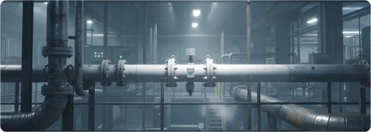
Vortex flowmeters are instruments that measure flow by detecting the frequency of vortices shed by a bluff body placed in the flow stream. Based on the Kármán vortex street principle, they are widely used for liquids, gases, and steam measurement. Their reliability, broad application range, and lack of moving parts make them highly valuable in industrial processes.

Metal Tube Flowmeters and Industrial Applications

WORKING PRINCIPLE

As fluid passes a bluff body in the pipe, vortices are shed alternately at regular intervals. The frequency of these vortices is directly proportional to the flow velocity.

Basic equation:
f = St · v / d
f: vortex frequency (Hz), St: Strouhal number (dimensionless), v: fluid velocity (m/s), d: bluff body width (m).

Flow rate is then calculated as:
Q = v · A
Q: flow rate (m³/s), A: pipe cross-sectional area (m²).

STRUCTURAL FEATURES

  • Bluff body: generates vortices
  • Sensors: piezoelectric, capacitive, or ultrasonic detection
  • Body: stainless steel or alloy materials
  • Output signals: Pulse, 4-20 mA, HART, Modbus, Profibus
  • Can be equipped with pressure and temperature compensation

ADVANTAGES AND LIMITATIONS

Advantages:

  • No moving parts, minimal maintenance
  • Suitable for liquids, gases, and steam
  • Can operate under high temperature and pressure
  • Wide measurement range

Limitations:

  • Cannot measure accurately at low Reynolds numbers (Re < 2000)
  • Sensitive to vibrations and noise
  • Accuracy decreases at low flow rates

APPLICATION AREAS

  • Steam measurement in power plants
  • Flow control in natural gas distribution networks
  • Process monitoring in chemical and petrochemical industries
  • Flow measurement in water and wastewater facilities
  • Liquid flow monitoring in food and beverage production

STANDARDS AND CALIBRATION

  • ISO 5167: Standards for flow measurement devices
  • ASME MFC-6: Standards for testing and calibration of vortex meters
  • AGA reports: Guidelines for gas flow measurement applications
  • Regular calibration is necessary to maintain accuracy

CONCLUSION

Vortex flowmeters are robust, versatile, and low-maintenance instruments widely used in modern industries. Their ability to integrate with digital communication protocols makes them a key component in process automation and industrial monitoring systems.

Ultrasonic flowmeters are modern instruments that measure flow using the propagation of sound waves. They are highly durable due to their non-intrusive design, require minimal maintenance, and can measure liquids, gases, and multiphase flows. They are widely used in water management, energy, petrochemical, food, and pharmaceutical industries.

Ultrasonic Flowmeters and Industrial Applications

WORKING PRINCIPLE

Ultrasonic flowmeters operate primarily using two methods: transit-time difference and Doppler effect.

• Transit-time method: Measures the difference in travel time between ultrasonic signals sent with and against the flow. This difference is proportional to flow velocity.

Basic equation:
v = (Δt · c²) / (2 · L · cosθ)
v: fluid velocity, Δt: time difference, c: speed of sound, L: distance between sensors, θ: angle of the signal

• Doppler method: Measures the frequency shift of sound waves reflected from particles or bubbles in the fluid. The shift is directly proportional to flow velocity.

STRUCTURAL FEATURES

  • Sensors: Mounted externally (clamp-on) or inserted into the pipe
  • Measurement range: from very low to high flow rates
  • Outputs: Pulse, 4-20 mA, HART, Profibus, Modbus
  • Data integration: Digital display and SCADA compatibility

ADVANTAGES AND LIMITATIONS

Advantages:

  • Non-intrusive measurement (clamp-on)
  • No moving parts, low maintenance
  • High accuracy (±0.5% – ±1)
  • Suitable for liquids, gases, and multiphase flows

Limitations:

  • Accuracy affected by fluid temperature, viscosity, and pipe material
  • Performance decreases in non-homogeneous flows
  • Doppler method requires particles or bubbles in the fluid

APPLICATION AREAS

  • Water and wastewater monitoring
  • Measurement in oil and gas pipelines
  • Cooling water control in power plants
  • Hygienic flow measurement in food and beverage industry
  • Process control in pharmaceutical production

STANDARDS AND CALIBRATION

  • ISO 6416: Standard for ultrasonic flow measurement
  • AGA reports: Gas measurement standards
  • ATEX-certified models for explosive environments
  • Regular calibration required to maintain accuracy

CONCLUSION

Ultrasonic flowmeters have become essential in modern industries thanks to their non-intrusive design, accuracy, and low maintenance requirements. Their ability to integrate with digital communication protocols makes them a reliable choice for process automation and optimization.

Metal tube flowmeters are robust instruments designed for accurate flow measurement under high pressure, high temperature, and aggressive fluid conditions. Compared to glass tube rotameters, they offer greater durability and are widely used in chemical, petrochemical, power generation, water treatment, food, and pharmaceutical industries.

Metal Tube Flowmeters and Industrial Applications

WORKING PRINCIPLE

They operate on the variable area principle. As the fluid flow increases, the float rises. In metal tube designs, the float position is detected either by magnetic sensors or mechanical indicators.

Fundamental equation:

Q = C · A(h) · √(2ΔP / ρ)

Q: flow rate, C: coefficient, A(h): cross-sectional area depending on float position, ΔP: pressure drop, ρ: fluid density.

STRUCTURAL FEATURES

  • Measuring tube: stainless steel or alloy steel
  • Float: selected with different densities for higher accuracy
  • Indicators: Mechanical (pointer type) or electronic (4-20 mA, HART, Profibus)
  • Operating range: up to 100 bar pressure and 400 °C temperature

ADVANTAGES AND LIMITATIONS

Advantages:

  • Reliable under harsh process conditions
  • Suitable for both liquids and gases
  • Easy integration with automation systems through electronic outputs

Limitations:

  • More expensive than glass tube models
  • Limited direct visual observation, relies on indicators

APPLICATION AREAS

  • Acid/alkali measurement in chemical and petrochemical plants
  • Steam and condensate flow monitoring in power plants
  • Chemical dosing control in water treatment facilities
  • Hygienic process monitoring in food and pharmaceutical industries

STANDARDS AND CALIBRATION

  • ISO 5167: Flow measurement standards
  • ASME MFC: Standards for flow measurement devices
  • ATEX-certified versions: For explosive atmospheres
  • Regular calibration required to maintain accuracy

CONCLUSION

Metal tube flowmeters play a vital role in modern industry due to their durability and reliability. By combining with digital technologies, they can be seamlessly integrated into automation systems, contributing to process optimization and efficiency.

Flow measurement is one of the most essential parameters in industrial processes. Accurate flow monitoring ensures energy optimization, process safety, and product quality. Variable area flowmeters, most commonly represented by rotameters, are widely used due to their simplicity and reliability.

Flow Measurement Techniques

WORKING PRINCIPLE

A variable area flowmeter consists of a tapered tube with a float inside. As fluid flows upward, the float rises until the upward force of the fluid balances with gravity. The position of the float corresponds to the flow rate, which can be read directly.

Q = C · A(h) · √(2ΔP / ρ)

Where Q is flow rate (m³/s), C is discharge coefficient, A(h) is the cross-sectional area depending on float height, ΔP is pressure drop, and ρ is fluid density.

MAIN COMPONENTS

  • Tapered glass or metal tube
  • Float element
  • Scale and indicator system
  • Optional: Electronic sensors and transmitter integration

ADVANTAGES AND LIMITATIONS

Advantages:

  • Simple and robust design
  • Direct visual reading
  • No external energy required

Limitations:

  • Sensitive to viscosity and density variations
  • Cannot be used in horizontal pipelines
  • Limited accuracy in high-precision processes

APPLICATION AREAS

  • Water and wastewater treatment plants
  • Chemical industry for liquids and gases
  • Laboratory environments for low flow rates
  • Food and pharmaceutical industries for basic process control

STANDARDS AND CALIBRATION

  • ISO 5167: Flow measurement devices
  • OIML R117: International metrology standard for liquid flow measurement devices
  • Periodic calibration is required to ensure accuracy

CONCLUSION

Variable area flowmeters remain widely used due to their low cost, simplicity, and reliability. The introduction of electronic rotameters has enabled digital monitoring and integration with SCADA systems, making them more versatile in modern industries.