Posts

Flow measurement is one of the most essential parameters in industrial processes. Accurate flow monitoring ensures energy optimization, process safety, and product quality. Variable area flowmeters, most commonly represented by rotameters, are widely used due to their simplicity and reliability.
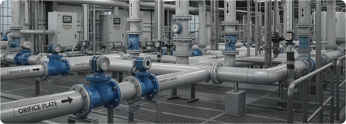
Flow Measurement Techniques

WORKING PRINCIPLE

A variable area flowmeter consists of a tapered tube with a float inside. As fluid flows upward, the float rises until the upward force of the fluid balances with gravity. The position of the float corresponds to the flow rate, which can be read directly.

Q = C · A(h) · √(2ΔP / ρ)

Where Q is flow rate (m³/s), C is discharge coefficient, A(h) is the cross-sectional area depending on float height, ΔP is pressure drop, and ρ is fluid density.

MAIN COMPONENTS

  • Tapered glass or metal tube
  • Float element
  • Scale and indicator system
  • Optional: Electronic sensors and transmitter integration

ADVANTAGES AND LIMITATIONS

Advantages:

  • Simple and robust design
  • Direct visual reading
  • No external energy required

Limitations:

  • Sensitive to viscosity and density variations
  • Cannot be used in horizontal pipelines
  • Limited accuracy in high-precision processes

APPLICATION AREAS

  • Water and wastewater treatment plants
  • Chemical industry for liquids and gases
  • Laboratory environments for low flow rates
  • Food and pharmaceutical industries for basic process control

STANDARDS AND CALIBRATION

  • ISO 5167: Flow measurement devices
  • OIML R117: International metrology standard for liquid flow measurement devices
  • Periodic calibration is required to ensure accuracy

CONCLUSION

Variable area flowmeters remain widely used due to their low cost, simplicity, and reliability. The introduction of electronic rotameters has enabled digital monitoring and integration with SCADA systems, making them more versatile in modern industries.
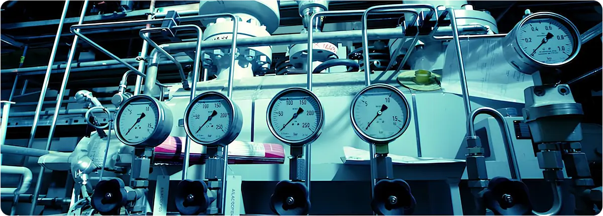
Flow measurement is one of the most fundamental parameters in industrial processes. Accurate flow measurement is essential for production efficiency, energy optimization, process safety, and product quality.

Flow Measurement Techniques

PRINCIPLES OF FLOW MEASUREMENT

Flow rate is defined as the quantity of fluid passing through a cross-sectional area. The basic formula is:

Q = A · v

Where Q is volumetric flow rate (m³/s), A is cross-sectional area (m²), and v is flow velocity (m/s).

Mass flow rate can be expressed as:

ṁ = ρ · Q

Where ṁ is mass flow rate (kg/s), ρ is fluid density (kg/m³).

TYPES OF FLOW MEASUREMENT DEVICES

  • Orifice Plates: Simple and cost-effective, but with higher pressure losses.
  • Venturi Tubes: Provide higher accuracy with lower pressure drop.
  • Pitot Tubes: Suitable for gases and low-viscosity fluids.
  • Electromagnetic Flowmeters: Highly accurate for conductive liquids.
  • Ultrasonic Flowmeters: Offer non-contact measurement.
  • Mass Flowmeters (Coriolis): Directly measure mass flow with high precision.

FACTORS AFFECTING MEASUREMENT ACCURACY

  • Changes in fluid temperature and viscosity
  • Pipe diameter and roughness
  • Installation position of the flowmeter
  • Calibration and maintenance issues

STANDARDS AND CALIBRATION

  • ISO 5167: For orifice, venturi, and nozzle-based flow measurement devices
  • ISO 4185: Standard for flowmeter calibration
  • ISO 17025: Accreditation for calibration laboratories

APPLICATION AREAS

  • Flow monitoring in water and wastewater treatment plants
  • Steam and fuel flow measurement in power plants
  • Reactor and pipeline flow control in chemical industries
  • Liquid flow control in food and beverage industries

CONCLUSION

Flow measurement systems are critical for ensuring reliable and efficient production in industrial plants. Proper device selection, correct installation, and regular calibration guarantee process continuity and safety.

Pressure measurement plays a vital role in industrial processes by ensuring safety, product quality, and energy efficiency. Inaccurate pressure readings can lead to equipment failures, production losses, and safety hazards. Therefore, the selection and use of the right pressure measurement systems are essential.

Pressure Measurement Systems and Transducers

PRINCIPLES OF PRESSURE MEASUREMENT

Pressure is defined as the force exerted per unit area:

P = F / A

Where P is pressure (Pa), F is force (N), and A is surface area (m²).

Types of pressure:

  • Absolute Pressure: Measured relative to a perfect vacuum.
  • Gauge Pressure: Measured relative to atmospheric pressure.
  • Differential Pressure: The difference between two pressure points.

TYPES OF PRESSURE SENSORS

  • Bourdon Tubes: Mechanical indicators, cost-effective but limited in precision.
  • Differential Pressure Transducers: Widely used for flow measurement and filter monitoring.
  • Piezoelectric Sensors: Provide high sensitivity for dynamic pressure changes.
  • Capacitive Pressure Sensors: Offer high accuracy and long-term stability.
  • Strain Gauge Sensors: Measure pressure through changes in electrical resistance.

FUNDAMENTAL EQUATIONS AND MEASUREMENT EXAMPLES

Hydrostatic pressure formula:

P = ρ · g · h

Where ρ is fluid density (kg/m³), g is gravitational acceleration (9.81 m/s²), and h is fluid height (m).

Flow rate derived from differential pressure:

Q = C · √ΔP

Where Q is flow rate (m³/s), C is the flow coefficient, and ΔP is the pressure difference (Pa).

FACTORS AFFECTING MEASUREMENT ACCURACY

  • Temperature variations and thermal drift
  • Sensor calibration and accuracy
  • Vibrations in the pipeline
  • Installation conditions and environmental influences

STANDARDS AND CALIBRATION

  • ISO 5167: Standard for differential pressure measurement devices.
  • IEC 61298: Defines test methods for pressure transducers.
  • ISO 17025: Accreditation requirements for calibration laboratories.

APPLICATION AREAS

  • Reactor pressure control in chemical industries
  • Steam line monitoring in power plants
  • Pipeline pressure monitoring in oil and gas sectors
  • Process pressure management in the food and beverage industry

CONCLUSION

Pressure measurement systems are critical to ensuring safety and efficiency in industrial plants. By selecting the appropriate sensor, performing regular calibration, and ensuring proper maintenance, processes can be managed reliably and sustainably.

Flow measurement is one of the most critical parameters in industrial processes. The amount, velocity, and characteristics of a fluid directly affect product quality and system efficiency in industries such as power generation, water treatment, petrochemicals, and food production.

Flow Measurement Techniques

FLOW CONCEPT AND BASIC FORMULA

Flow (Q) is the volume of fluid passing through a cross-section per unit of time.

Formula:
Q = A · v

Where Q (m³/s) is the flow rate, A (m²) is the pipe cross-sectional area, and v (m/s) is the average velocity.

The Bernoulli principle, which describes the conservation of energy in a fluid, forms the basis of many flow measurement techniques.

MECHANICAL MEASUREMENT METHODS

• Orifice Plate: Based on pressure drop; a cost-effective but less accurate method.
• Venturi Tube: Provides higher accuracy with minimal pressure loss.
• Pitot Tube: Commonly used for velocity measurement.
These methods are defined under ISO 5167 standards.

MODERN FLOW MEASUREMENT TECHNOLOGIES

• Ultrasonic Flowmeter: Measures the effect of the fluid on sound waves; has no moving parts.
• Magnetic Flowmeter: Works on electromagnetic induction principle; suitable for conductive fluids.
• Mass Flowmeter (Coriolis): Directly measures mass flow with high accuracy, widely used in critical applications.

FACTORS AFFECTING MEASUREMENT ACCURACY

• Fluid viscosity
• Changes in temperature and density
• Turbulence within the pipeline
• Installation conditions and sensor placement

Ignoring these factors may result in significant measurement errors.

CALIBRATION AND STANDARDS

Regular calibration of flow measurement devices is necessary. ISO 5167 defines calibration methods for differential pressure devices such as orifice and Venturi tubes. Additionally, AGA reports (e.g., AGA3) are widely applied in natural gas flow measurement.

INDUSTRIAL APPLICATIONS

• Monitoring liquid and gas flows in petrochemical industries
• Steam and water flow control in power plants
• Inlet/outlet flow monitoring in water treatment plants
• Accurate liquid measurement in food industry processes

CONCLUSION

Accurate flow measurement is essential for process safety and efficiency. Proper device selection, compliance with standards, calibration, and correct installation conditions ensure reliable and sustainable operation of industrial facilities.