Posts

Pump and valve systems are at the core of industrial and municipal operations, from water distribution and wastewater treatment to oil refining and power generation. While these systems ensure reliable fluid transport and process control, they also account for a significant portion of global electricity consumption. According to the International Energy Agency (IEA), pumps alone represent 10–15% of global electricity usage, and industrial facilities dedicate 20–30% of their total electricity consumption to pumping processes.

This substantial energy demand presents both a challenge and an opportunity: improving pump and valve system efficiency can save billions in electricity costs while significantly reducing carbon emissions.

Improving the Efficiency and Reliability of Vertical Pumps

GLOBAL SHARE OF ENERGY CONSUMPTION

  • Industrial perspective: Pumps represent 25–40% of motor-driven electricity use in chemicals, pulp & paper, and mining sectors.
  • Municipal water and wastewater: Approximately 50% of operational costs in wastewater plants come from pumping.
  • Overall impact: If pumps globally operated at optimum efficiency, global electricity demand could drop by 4–5%, equivalent to the output of 200–250 nuclear power plants.

PUMP POWER CALCULATION

P = (Q × H × ρ × g) / η

  • P = Pump power (W)
  • Q = Flow rate (m³/s)
  • H = Pump head (m)
  • ρ = Fluid density (kg/m³)
  • g = Acceleration due to gravity (9.81 m/s²)
  • η = Overall pump and motor efficiency

ENERGY LOSSES IN PUMP AND VALVE SYSTEMS

  • Incorrect pump sizing leading to low-efficiency partial-load operation.
  • Flow throttling with valves causing unnecessary pressure losses.
  • Poor pipeline design with excessive bends, small diameters, or rough surfaces.
  • Lack of maintenance such as worn impellers, clogged filters, or leaking valves.

ROLE OF VALVES IN ENERGY EFFICIENCY

  • Control valves with high pressure drop increase pump workload.
  • Check valves prevent reverse flow and reduce energy losses.
  • Smart valves with positioners enable optimized flow control, saving up to 10–15% energy.

STRATEGIES TO IMPROVE EFFICIENCY

  • Proper pump selection to match actual system demand.
  • Use of variable frequency drives (VFDs) for optimal pump speed control.
  • Hydraulic optimization including proper pipe sizing and reduced pressure drops.
  • Regular maintenance such as impeller cleaning and valve seat replacement.
  • Digital monitoring with IoT sensors and digital twins for real-time performance tracking.

ENERGY CONSUMPTION DISTRIBUTION (TYPICAL)

  • Pump hydraulic inefficiency: 20–30%
  • Motor inefficiency: 5–10%
  • Throttling via valves: 10–20%
  • Pipeline friction losses: 10–15%
  • Other operational factors: 5–10%

POTENTIAL GLOBAL BENEFITS

  • Economic savings exceeding $50 billion annually with high-efficiency systems.
  • Environmental impact: more than 1 gigaton of CO₂ reduction per year.
  • Operational reliability through reduced wear and extended equipment life.

CONCLUSION

Pump and valve systems offer one of the largest opportunities for improving industrial energy efficiency. Through smart pump selection, efficient valve design, and advanced digital monitoring, industries can significantly reduce electricity consumption, cut operational costs, and support global sustainability objectives.
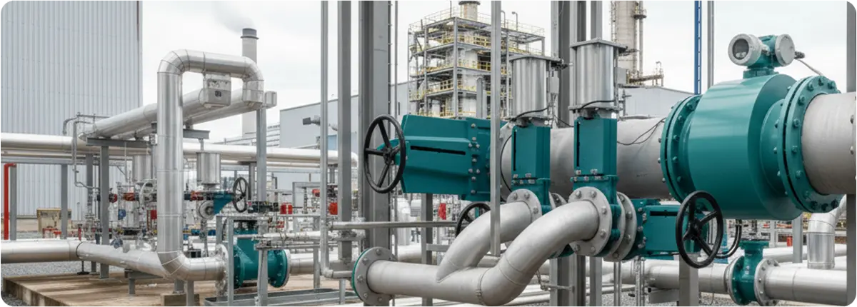
Knife gate valves are a specialized type of shut-off valve designed to handle fluids with suspended solids, slurries, or fibrous materials. Unlike standard gate valves, which use a wedge-shaped gate, knife gate valves use a thin, sharp-edged blade that can cut through thick media, making them indispensable in industries such as wastewater treatment, mining, pulp & paper, and chemical processing.

Knife Gate Valves

WORKING PRINCIPLE

The core principle of a knife gate valve is simple yet effective. When actuated, a flat blade (the ‘knife’) slides down into the valve seat, cutting through the media and forming a tight seal. In the open position, the blade retracts completely, allowing for a nearly unobstructed flow path.

  • Open position: Full-bore flow with minimal pressure drop.
  • Closed position: The knife-shaped disc cuts through solids, providing reliable shutoff.

DESIGN FEATURES

Knife gate valves are built for durability in harsh operating environments:

  • Body construction: Typically cast iron, ductile iron, carbon steel, or stainless steel.
  • Gate design: Sharp-edged stainless steel blade to shear through solids.
  • Seat options: Soft seats (elastomer, PTFE) for tight shutoff, or metal seats for high-temperature/abrasive applications.
  • Actuation: Manual (handwheel), pneumatic, hydraulic, or electric actuators.
  • Sizes & ratings: DN 50–DN 1200, usually up to PN 10 or ANSI Class 150.

APPLICATIONS

  • Wastewater treatment plants: Managing sludge and thick waste streams.
  • Mining industry: Controlling abrasive slurries of ore, sand, and tailings.
  • Pulp & paper mills: Handling fibrous pulp mixtures.
  • Chemical industry: Managing corrosive fluids with solid particles.
  • Food industry: Processing thick pastes, starches, or viscous ingredients.

ADVANTAGES

  • Cuts through solids and fibrous materials.
  • Compact design with minimal space requirements.
  • Low-pressure drop when fully open.
  • Cost-effective for large-diameter pipelines.
  • Easy to maintain with replaceable seats and seals.

LIMITATIONS

  • Not suitable for high-pressure applications above PN 10.
  • Slower operation compared to quarter-turn valves.
  • Not ideal for throttling; mainly on/off service.
  • Seat wear with abrasive slurries requires maintenance.

SELECTION CRITERIA

Factors to consider:

  1. Media characteristics: solids, abrasiveness, chemical composition.
  2. Pressure and temperature ratings.
  3. Actuation method: manual vs. automated.
  4. Sealing requirements: soft seats vs. metal seats.
  5. Installation space: vertical installation recommended.

COMPARISON WITH STANDARD GATE VALVES

  • Knife gate valve: Designed for slurry and solids, sharper disc, low-pressure ratings.
  • Standard gate valve: Designed for clean liquids and gases, higher pressure ratings, wedge-shaped gate.

ENGINEERING NOTES

The flow coefficient (Cv) of a knife gate valve is relatively high in the fully open position:

Q = Cv * sqrt(ΔP / SG)

  • Q = Flow rate (GPM)
  • Cv = Valve flow coefficient
  • ΔP = Pressure drop (psi)
  • SG = Specific gravity of fluid

Recommended slurry velocity: 1.5–3.5 m/s.

CONCLUSION

Knife gate valves play a vital role in industries dealing with challenging fluids. Their unique design enables them to handle slurries, viscous materials, and fibrous suspensions effectively. Proper selection ensures reliable operation, safety, and long service life.