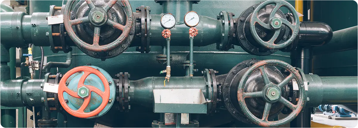
Natural gas pressure reduction stations (PRS) are critical facilities that reduce the high-pressure gas delivered through transmission pipelines to safe levels for city networks and industrial plants. However, these operations involve significant energy consumption—mainly from heating systems, regulators, compressors, and control equipment. Rising energy costs and global commitments to reduce carbon emissions make energy efficiency and optimization strategies essential for modern PRS facilities.

SOURCES OF ENERGY CONSUMPTION
Regulators and Heating Systems
When natural gas pressure is reduced, it experiences cooling due to the Joule–Thomson effect. To prevent condensation and freezing in downstream pipelines, gas heaters are used. These heating systems are often the largest energy consumers in PRS.
Compressors and Pumps
Some stations employ pumps or compressors to maintain pressure balance or direct gas toward measurement systems. These units significantly contribute to electrical energy consumption.
SCADA and Automation Systems
Although their share is smaller, SCADA servers, sensors, and controllers add to the station’s continuous energy load.
METHODS FOR IMPROVING ENERGY EFFICIENCY
Waste Heat Recovery Systems
By recovering heat from exhaust gases or flue gases, PRS can reduce the energy demand of heating systems. Heat recovery exchangers are increasingly being adopted to improve efficiency.
High-Efficiency Heaters
• Condensing boilers and high-performance heat exchangers offer up to 15–20% higher efficiency compared to conventional units.
• In some European PRS facilities, heat exchanger-based systems have replaced electric heaters, cutting costs and emissions.
Power Generation from Pressure Energy (Turboexpanders)
As natural gas expands from high to low pressure, it carries significant potential energy, which can be harnessed using turboexpanders.
• Benefit: Electricity production for station self-consumption or supply to the grid.
• Capacity: Installations can generate 10–20 MW of power, depending on flow and pressure conditions.
Preventing Gas Leaks
Even minor leaks from valves, seals, or joints cause substantial energy losses over time. Leak flow rates can be calculated using the orifice equation:
Q = Cd · A · √(2 · ΔP / ρ)
Routine tightness testing and predictive maintenance help eliminate such inefficiencies.
Smart Control Algorithms
• By integrating AI-driven optimization into SCADA systems, PRS facilities can minimize unnecessary heating and energy losses.
• Example: Adjusting regulator valve operation in gradual steps prevents sudden cooling, thereby reducing heater load.
ENGINEERING CALCULATIONS
Energy Released During Pressure Reduction
W = ṁ · R · T · ln(Pin / Pout)
• ṁ: Mass flow rate (kg/s)
• R: Gas constant (J/kg·K)
• T: Absolute temperature (K)
• Pin, Pout: Inlet and outlet pressure (Pa)
This formula is commonly used to estimate the electrical generation potential of turboexpander systems.
Heat Consumption for Gas Reheating
Q = ṁ · Cp · ΔT
• Cp: Specific heat capacity of gas
• ΔT: Required temperature increase
REAL-WORLD APPLICATIONS
• Turkey: BOTAŞ city gate stations are implementing condensing boiler systems to lower heating demand.
• Europe (Italy, Germany): Turboexpanders are installed in several PRS to generate millions of kWh annually from pressure energy.
• Japan: AI-based SCADA systems have enabled 15–20% reductions in energy use in PRS operations.
CONCLUSION
Energy efficiency in natural gas pressure reduction stations is both an economic opportunity and an environmental necessity. Strategies such as:
• Efficient valves and heaters
• Heat recovery systems
• Turboexpander-based power generation
• Leak prevention and smart automation
can deliver up to 20% energy savings.
In the future, the integration of artificial intelligence and digital twin technology is expected to push energy optimization in PRS even further, ensuring both cost savings and environmental benefits.
