Posts

In industrial process automation, monitoring and controlling liquid levels is essential for both operational safety and efficiency. Level gauges and controllers play a critical role in ensuring accurate measurement, preventing overflow, protecting pumps from dry running, and maintaining stable process conditions. Depending on the industry—whether it is chemical, oil and gas, food and beverage, power generation, or water treatment—different types of level gauges and controllers are deployed to suit specific operational requirements.

Level Gauges & Controllers

TYPES OF LEVEL GAUGES

  1. Sight Glass Level Gauges
    • A transparent tube or glass window that shows the actual liquid level inside a tank.
    • Advantages: Direct reading, simple construction, reliable for non-hazardous fluids.
    • Limitations: Not suitable for high-pressure, high-temperature, or corrosive media.
  2. Magnetic Level Gauges
    • Operate on the principle of magnetic coupling, using a float containing a magnet that moves with the liquid level.
    • The position of the float is tracked by an external indicator or sensor.
    • Benefits: Safe for high-pressure and high-temperature applications, can be combined with switches and transmitters for automation.
  3. Reflex and Transparent Gauges
    • Designed for high-pressure steam or chemical service.
    • Reflex gauges use prism glass to enhance the visibility of the liquid column.
    • Transparent gauges allow the use of backlighting to improve readability.

LEVEL CONTROLLERS

Level controllers ensure automatic regulation of liquid levels in tanks or vessels. They are often integrated with transmitters, relays, and actuators to maintain process stability.

  • On/Off Controllers: Trigger pumps, solenoid valves, or alarms when the level reaches a set point.
  • Proportional Controllers: Adjust the flow of inlet or outlet valves gradually, maintaining stable liquid levels.
  • Smart Controllers: Equipped with microprocessors, enabling digital communication, diagnostics, and predictive maintenance.

KEY ENGINEERING CONSIDERATIONS

When selecting and designing level gauges and controllers, several parameters should be evaluated:

  1. Process Conditions
    • Temperature (°C or °F)
    • Pressure (bar or psi)
    • Chemical compatibility with gauge materials
  2. Accuracy and Range
    • For critical applications such as dosing, an accuracy of ±0.25% may be required.
    • Range should be chosen according to vessel dimensions.
  3. Safety Standards
    • Compliance with ASME, API, or IEC standards depending on industry.
    • Explosion-proof and flameproof designs for hazardous areas.
  4. Maintenance and Reliability
    • Magnetic level gauges and smart controllers reduce downtime through self-diagnostics.
    • Corrosion-resistant materials (e.g., stainless steel 316L, Hastelloy) ensure durability.

EXAMPLE APPLICATION IN WATER TREATMENT PLANT

Consider a clarifier tank in a municipal water treatment facility:

  • Magnetic level gauge provides continuous monitoring.
  • Level switch integrated with the controller prevents overflow by activating pumps when the tank is nearly full.
  • Smart level controller communicates with the SCADA system, optimizing pump cycles and saving energy.

ADVANTAGES OF USING LEVEL GAUGES & CONTROLLERS

  • Operational Safety: Prevents overflow, leakage, or pump cavitation.
  • Process Optimization: Maintains consistent product quality.
  • Energy Efficiency: Intelligent control reduces unnecessary pumping cycles.
  • Versatility: Applicable across multiple industries and for various types of fluids.

CONCLUSION

Level gauges and controllers are indispensable components of process automation systems. From simple sight glasses to advanced magnetic and electronic controllers, these instruments safeguard processes, improve efficiency, and reduce operational costs. Careful selection based on process requirements, material compatibility, and safety standards ensures reliable and long-lasting performance.

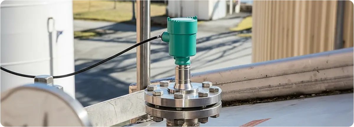
Radar level transmitters are non-contact measurement devices that use electromagnetic waves to measure the level of liquids and solids. Compared to ultrasonic and hydrostatic measurement methods, they provide higher accuracy and ensure reliable performance even under harsh process conditions.

Radar Level Transmitters

WORKING PRINCIPLE

Radar transmitters emit microwave signals toward the material surface and measure the time taken for the reflected signal to return.

Formula: d = (c × t) / 2

Where:
d: distance (m)
c: speed of light (3 × 10⁸ m/s)
t: round-trip time (s)

The difference between the tank height and this measured distance provides the actual material level. Modern 24 GHz and 80 GHz radar technologies offer superior resolution and narrower beam angles.

TYPES OF RADAR

  • Guided Wave Radar (GWR): Uses a probe or cable to guide the signal, ideal for tanks with foam, vapor, or dust.
  • Non-Contact Radar: Uses an antenna to transmit signals, suitable for high-pressure, high-temperature, and aggressive chemical environments.

STRUCTURAL FEATURES

  • Body materials: stainless steel, PTFE coating
  • Output signals: 4-20 mA, HART, Modbus, Profibus
  • Protection class: IP67 – IP68
  • Explosion-proof versions (ATEX & IECEx)
  • Accuracy up to ±2 mm

ADVANTAGES AND LIMITATIONS

Advantages:

  • Minimal influence from foam, vapor, and dust
  • High accuracy and reliability
  • Long measuring range (up to 70 m)
  • Withstands harsh process conditions

Limitations:

  • Proper antenna alignment and mounting are critical
  • Build-up on antenna surfaces may affect accuracy
  • Generally more expensive than ultrasonic methods

SELECTION CRITERIA

  • Tank height and geometry
  • Physical properties of the measured material
  • Process conditions (temperature, pressure, vapor, dust)
  • Communication protocol requirements
  • Desired measurement accuracy

APPLICATION AREAS

  • Chemical and petrochemical industries
  • Oil and gas storage tanks
  • Power plants
  • Food and beverage industry (hygienic design models)
  • Water and wastewater treatment plants

STANDARDS

  • IEC 61326 (electromagnetic compatibility)
  • ATEX & IECEx certifications (for explosive atmospheres)
  • EHEDG (hygienic design – food industry)

CONCLUSION

Radar level transmitters are among the most preferred measurement devices in modern industry due to their non-contact measurement capability, high accuracy, and robustness under challenging process conditions.

Ultrasonic level transmitters are non-contact measurement devices that use sound waves to determine the level of liquids and solids. They provide reliable measurement in tanks, silos, and open areas. Compared to radar, capacitive, or hydrostatic methods, they are often more cost-effective and easier to install, making them highly popular across industries.

Ultrasonic Level Transmitters

WORKING PRINCIPLE

The sensor emits ultrasonic pulses toward the material surface. The time taken for the waves to return is measured, and the distance is calculated to determine the level.

Basic formula: d = (c × t) / 2

Where:
d: distance (m)
c: speed of sound (343 m/s in air)
t: round-trip time (s)

The difference between tank height and this distance gives the material level.

STRUCTURAL FEATURES

  • Measuring range: 0.2 m – 70 m
  • Body materials: PVDF, stainless steel, PP
  • Output signals: 4-20 mA, HART, Modbus, Profibus
  • Protection class: IP67 – IP68
  • ATEX and IECEx certified models

ADVANTAGES AND LIMITATIONS

Advantages:

  • Non-contact measurement, no corrosion risk
  • Easy installation and minimal maintenance
  • Suitable for dusty and aggressive environments
  • Flexible for various tank geometries

Limitations:

  • Foam and vapor can affect measurement accuracy
  • Narrow tanks may cause reflection issues
  • Temperature fluctuations influence sound velocity

SELECTION CRITERIA

  • Tank height and geometry
  • Physical properties of the measured medium
  • Environmental conditions (temperature, pressure, humidity)
  • Communication protocols
  • Explosion-proof certifications (ATEX, IECEx)

APPLICATION AREAS

  • Water and wastewater treatment plants
  • Food and beverage industry
  • Chemical industry (corrosive liquid storage)
  • Cement and mining (solid storage silos)
  • Power plants (ash, coal, and liquid tanks)

STANDARDS

  • IEC 61010 (safety for measurement devices)
  • ATEX & IECEx certifications
  • NAMUR NE 107 (diagnostic status)

CONCLUSION

Ultrasonic level transmitters are widely used in industrial facilities due to their non-contact measurement advantages and durability. Proper selection and installation help reduce operating costs while increasing process reliability.

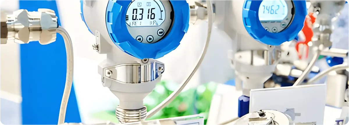
Smart pressure transmitters represent the evolution of traditional pressure measurement devices, integrating advanced sensors, microprocessors, and digital communication protocols. They not only measure pressure but also provide self-diagnostics, remote monitoring, and seamless integration with advanced control systems, enhancing process safety, energy efficiency, and reducing maintenance costs.

Pressure Transmitters

WORKING PRINCIPLE

Smart pressure transmitters operate by converting applied pressure into an electrical signal through a diaphragm and sensing element. The most common sensor technologies include:

  • Piezoresistive sensors
  • Capacitive sensors
  • Piezoelectric sensors
  • Strain gauge elements

The analog signals are digitized by microprocessors, processed, filtered, and then transmitted to control systems.

Basic equation:
P = F / A
P: Pressure (Pa)
F: Force (N)
A: Area (m²)

STRUCTURAL FEATURES

  • High-quality diaphragm materials (stainless steel, tantalum, monel, ceramic)
  • Microprocessor-based electronics
  • Output protocols: 4-20 mA, HART, Profibus, Fieldbus, Modbus, WirelessHART
  • Protection ratings: IP65 – IP68
  • Explosion-proof models (ATEX, IECEx)

SMART FUNCTIONS

  • Self-diagnosis for malfunction detection
  • Predictive maintenance
  • Remote monitoring and calibration
  • Data logging and trend analysis
  • Automatic zero/span adjustment
  • Integration with SCADA/DCS systems

SELECTION CRITERIA

  • Measurement range and accuracy
  • Process environment (temperature, pressure, chemical compatibility)
  • Communication protocols
  • Certifications (ATEX, SIL, CE)
  • Mounting options and mechanical strength

ADVANTAGES AND LIMITATIONS

Advantages:

  • High accuracy and long-term stability
  • Remote access and data analytics
  • Reduced maintenance costs
  • Ready for Industry 4.0 and IIoT integration

Limitations:

  • Higher initial cost
  • Requires specialized configuration
  • Cybersecurity risks

APPLICATION AREAS

  • Oil and gas industry (pipelines, refineries)
  • Chemical plants (reactor pressure monitoring)
  • Power plants (boiler and turbine monitoring)
  • Food and pharmaceutical industry (hygienic processes)
  • Water and wastewater treatment facilities

STANDARDS AND CALIBRATION

  • IEC 61508 (SIL certification)
  • NAMUR NE107 (diagnostic status)
  • ISO/IEC 17025 (calibration)
  • Hart and Fieldbus compliance standards

CONCLUSION

Smart pressure transmitters are essential devices for modern industrial automation, combining safety, efficiency, and digitalization. When properly selected and applied, they offer significant long-term benefits to industries.

Pressure transmitters are essential instruments used in industrial facilities to enhance process safety and efficiency. They convert pressure into standardized electrical signals (e.g., 4-20 mA) and transmit them to control systems. They are widely applied in oil and gas, chemical, energy, food, pharmaceutical, water, and wastewater industries.

WORKING PRINCIPLE

The operating principle of a pressure transmitter is based on the deformation or electrical variation caused by applied pressure. The main measurement technologies include:

  • Strain gauge: measures resistance changes due to diaphragm deformation.
  • Piezoresistive sensors: rely on resistance changes in semiconductor materials.
  • Capacitive sensors: measure capacitance changes as the diaphragm moves.
  • Piezoelectric sensors: generate voltage proportional to applied pressure.

Basic equation:
P = F / A
P: Pressure (Pa)
F: Force (N)
A: Area (m²).

This principle ensures accurate and repeatable conversion of applied pressure into electrical signals.

STRUCTURAL FEATURES

  • Housing: stainless steel, aluminum, or special alloys
  • Diaphragm: stainless steel, monel, tantalum, ceramic
  • Electronics: analog/digital signal processing
  • Output signals: 4-20 mA, HART, Fieldbus, Profibus
  • Protection ratings: IP65 – IP68
  • Explosion-proof models (ATEX, IECEx)

TYPES OF PRESSURE TRANSMITTERS

  • Gauge pressure transmitters: measure pressure relative to atmospheric pressure.
  • Absolute pressure transmitters: measure relative to a vacuum reference.
  • Differential pressure transmitters: measure pressure difference between two points, commonly used in flow measurement.
  • Multivariable transmitters: measure pressure, temperature, and flow simultaneously.

SELECTION CRITERIA

Key factors when selecting a pressure transmitter include:

  • Measurement range (rangeability)
  • Accuracy class
  • Process temperature and pressure
  • Material compatibility
  • Output communication protocols
  • Certifications (ATEX, SIL, CE)
  • Mounting type (flanged, threaded, manifold connection)

ADVANTAGES AND LIMITATIONS

Advantages:

  • High accuracy and reliability
  • Wide measurement range
  • Digital communication integration
  • Long-term stability

Limitations:

  • Regular calibration required
  • Special diaphragms needed for abrasive or high-temperature media
  • Can be costly depending on specifications

APPLICATION AREAS

  • Pressure monitoring in oil and gas pipelines
  • Reactor pressure in chemical plants
  • Boiler pressure in power plants
  • Pump pressure in water and wastewater plants
  • Hygienic pressure measurement in food and pharmaceutical industries

STANDARDS AND CALIBRATION

  • IEC 61508 (SIL – Safety Integrity Level)
  • NAMUR NE43 (fault signal handling)
  • ISO/IEC 17025 (calibration)
  • OIML R 117 (measurement standards)

Regular calibration is essential for maintaining reliable measurement over time.

CONCLUSION

Pressure transmitters are indispensable devices for industrial automation and process safety. When properly selected, they enhance both safety and efficiency in industrial operations.

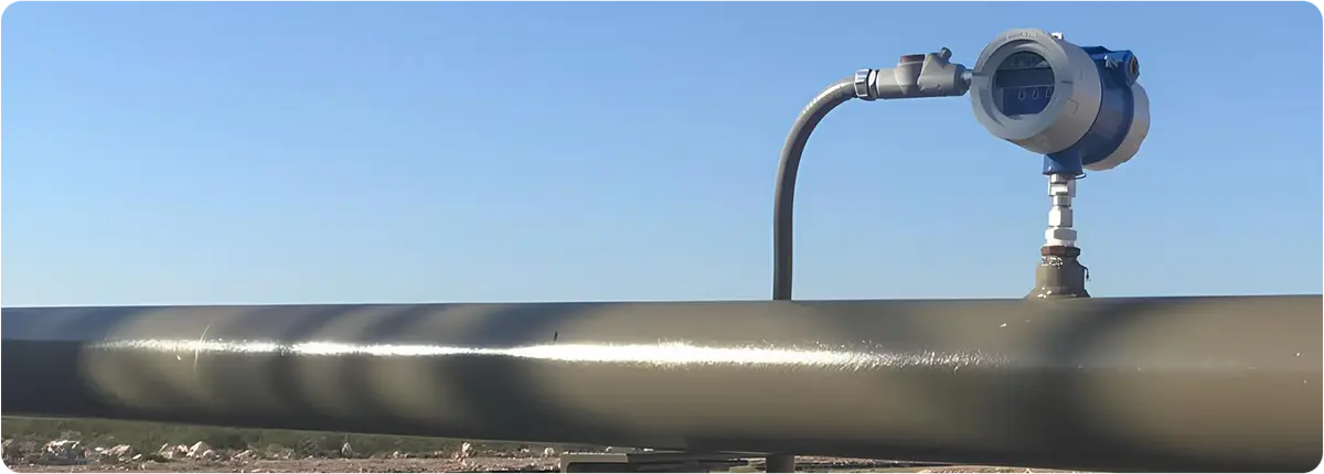
Thermal mass flowmeters are devices that measure mass flow using the principle of heat transfer. They are particularly effective for gas measurement, providing high accuracy in industries such as chemicals, energy, environmental technologies, HVAC, and process control. With no moving parts, they offer low maintenance and long service life.

Thermal Mass Flowmeters

WORKING PRINCIPLE

Thermal mass flowmeters work by measuring the amount of heat carried away from a heated sensor by the flowing fluid. Two main principles are applied:

  • Convective heat transfer: The heater element is kept at a constant temperature, and the heat carried away by the fluid is proportional to flow velocity.
  • Differential temperature method: The temperature difference between two sensors is measured and correlated to flow.

Basic equation:
Qm = k · ΔT
Qm: mass flow rate (kg/h), k: calibration constant, ΔT: temperature difference (°C).

STRUCTURAL FEATURES

  • Sensors: heating element and reference temperature sensors
  • Materials: Stainless steel, Inconel, Teflon coatings
  • Output signals: 4-20 mA, Pulse, HART, Profibus, Modbus
  • Optional pressure and temperature compensation
  • ATEX-certified models for explosive environments

ADVANTAGES AND LIMITATIONS

Advantages:

  • Direct mass flow measurement (no density compensation required)
  • High accuracy (typically 1% – 2%)
  • No moving parts, minimal maintenance
  • Wide measurement range

Limitations:

  • Accuracy may be reduced in dusty or particulate-laden flows
  • Primarily limited to gas measurement
  • Limitations under very high pressure and temperature conditions

APPLICATION AREAS

  • Natural gas and biogas measurement
  • Airflow control in HVAC systems
  • Chemical and petrochemical processes
  • Emission monitoring in environmental technologies
  • Combustion control in power plants

STANDARDS AND CALIBRATION

  • ISO 14511: Standard for thermal flowmeters
  • EPA and TÜV certified models for emission measurement
  • ATEX certification for explosive environments
  • Regular calibration is essential for maintaining accuracy

CONCLUSION

Thermal mass flowmeters are vital instruments for gas flow measurement, offering high accuracy, low maintenance, and broad industrial applicability. Their compatibility with digital communication protocols ensures seamless integration into modern process automation systems.

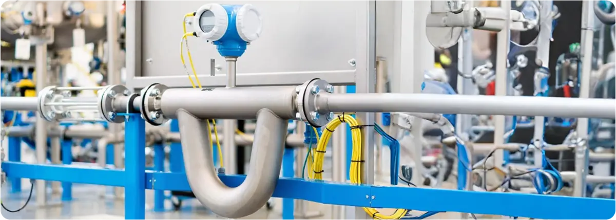
Coriolis flowmeters are among the most accurate instruments for directly measuring mass flow. Based on the Coriolis effect, these devices can simultaneously measure additional parameters such as fluid density, temperature, and viscosity. Due to their unmatched accuracy, they are widely used in chemical, petrochemical, food, pharmaceutical, energy, and oil & gas industries.

Coriolis Flowmeters

WORKING PRINCIPLE

Coriolis flowmeters measure mass flow by detecting the phase shift caused when fluid passes through vibrating tubes. The tubes are set into oscillation by electromagnetic drivers. As the fluid flows, a measurable phase difference appears between the inlet and outlet ends of the tube, which is proportional to the mass flow.

Basic equation:
ṁ = k · Δφ
ṁ: mass flow rate (kg/s), k: calibration constant, Δφ: phase shift (radians).

Additionally, the natural vibration frequency of the tubes is used to measure fluid density:
ρ = f(ω)
ρ: density, ω: vibration frequency.

STRUCTURAL FEATURES

  • Measuring tubes: U-shaped or dual straight tube designs
  • Materials: Stainless steel, Hastelloy, or corrosion-resistant alloys
  • Sensors: Electromagnetic or optical detection
  • Output: 4-20 mA, HART, Profibus, Modbus, Foundation Fieldbus
  • Additional functions: Density, temperature, and viscosity measurement

ADVANTAGES AND LIMITATIONS

Advantages:

  • Direct mass flow measurement
  • Very high accuracy (±0.1% – ±0.2%)
  • Simultaneous density and temperature measurement
  • No moving parts, minimal maintenance

Limitations:

  • High initial cost
  • Heavy and expensive for large pipe diameters
  • Sensitive to vibrations and installation conditions

APPLICATION AREAS

  • Chemical and petrochemical industry: measurement of acids, bases, and solutions
  • Oil and gas industry: mass flow measurement
  • Food and beverage production: sugar solutions, milk, beer, etc.
  • Pharmaceutical industry: precise formulations
  • Energy sector: fuel feed and process control

STANDARDS AND CALIBRATION

  • ISO 10790: International standard for Coriolis flowmeters
  • OIML R 137: International standard for gas flow measurement devices
  • ATEX-certified versions: For explosive environments
  • Regular calibration is essential to maintain accuracy

CONCLUSION

Coriolis flowmeters provide unmatched accuracy and versatility by offering direct mass flow measurement combined with density and temperature monitoring. They are indispensable instruments in modern process industries, particularly where precision and reliability are critical.

In industrial fluid control systems, actuators play a vital role in the operation of butterfly valves. The right actuator ensures faster opening and closing cycles, allows for precise and incremental flow regulation, and ultimately improves overall system efficiency. By delivering the necessary torque, actuators make it possible to operate valves reliably, safely, and in a way that supports continuous operations.

Below is an overview of the main actuator types used in industrial butterfly valves, along with their applications and important selection factors.

Dogru Ürün Seçimi

MANUAL ACTUATORS

Manual actuators are the simplest type, operated using a handwheel, lever, or crank. They require no external power source and are ideal for systems where access is easy and automation is not necessary.

For larger butterfly valves, gear mechanisms are often used to increase torque, and advanced models may include analog position indicators for the valve disc.

  • Pros: Low cost, simple design, easy maintenance
  • Cons: Suitable only for smaller valves, slow actuation speed, limited use in critical pipelines

ELECTRIC ACTUATORS

Electric actuators use a bidirectional motor to open and close valves remotely. Integrated gearboxes reduce motor speed and increase torque output. These actuators are generally low-maintenance, energy-efficient, and operate quietly, making them suitable for process control in light-duty or non-critical applications.

Many electric actuators are equipped with limit switches to automatically stop the motor when the valve is fully open or closed.

  • Pros: Remote operation, quiet and clean operation, low power consumption
  • Cons: Requires a stable power supply, limited torque for heavy-duty applications

PNEUMATIC ACTUATORS

Pneumatic actuators operate using compressed air and can be single-acting (spring return) or double-acting. When air enters the actuator chamber, it moves a piston or plunger, producing linear or rotary motion that turns the valve disc.

These actuators are compact, lightweight, cost-effective, and provide rapid response times. They are widely used in frequently cycled pipelines such as gas distribution, steam lines, and slurry transport.

  • Pros: Fast actuation, lightweight, cost-efficient
  • Cons: Requires a dedicated compressed air supply

HYDRAULIC ACTUATORS

Hydraulic actuators are designed for large-diameter or high-pressure pipelines where high torque is essential. They operate using hydraulic oil or, in some cases, water. Available in both single-acting (spring return) and double-acting designs, hydraulic actuators can handle the most demanding industrial valve applications.

  • Pros: High torque capability, suitable for heavy-duty service
  • Cons: More complex maintenance, requires fluid management and leak prevention

FIVE KEY FACTORS TO CONSIDER WHEN CHOOSING A BUTTERFLY VALVE ACTUATOR

  • Duty Cycle: Indicates how frequently an actuator can operate before overheating or wearing out. Hydraulic actuators can operate with nearly a 100% duty cycle, ideal for high-frequency, high-pressure systems. Electric actuators may have lower duty cycles, around 25%, for intermittent operation.
  • Actuation Speed: Fast-acting actuators (hydraulic or pneumatic) are preferred for critical operations. Slow-operating actuators may be better for processes requiring gradual valve movement.
  • Process Media Characteristics: The type of fluid being handled—whether corrosive, toxic, or gaseous—determines actuator material requirements. The actuator housing should be as robust as or more durable than the valve body.
  • Safety and Redundancy: Fail-safe features, such as spring-return mechanisms, are essential in critical systems. For example, a fail-open hydraulic butterfly valve ensures the line remains uncontaminated in case of actuator failure.
  • Cost and Maintenance: Total cost includes purchase price, maintenance, and spare parts. Pneumatic actuators generally have longer service lives but require additional equipment like air compressors.

CONCLUSION

Choosing the right actuator for butterfly valves directly affects system performance, operational safety, and maintenance costs. Matching the actuator to system demands, fluid characteristics, and budget constraints ensures reliable operation, reduces downtime, and improves overall process efficiency.