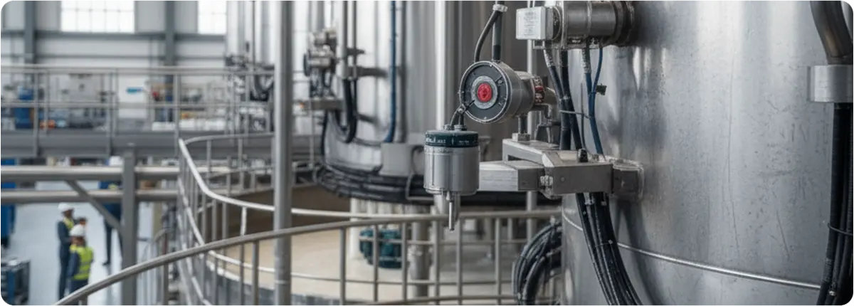
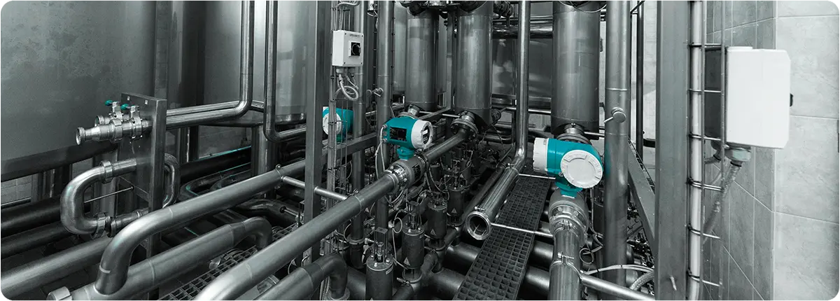
In industrial plants, accurate level measurement of liquids, solids, and semi-solids is vital for process safety, quality control, and operational continuity. Among the available technologies, capacitive level transmitters stand out due to their high accuracy, robust design, and broad range of applications. These devices are widely used in industries such as food, chemicals, petrochemicals, cement, pharmaceuticals, and energy.

WORKING PRINCIPLE
Capacitive level transmitters operate on the principle of capacitance change. Essentially, the system functions as follows:
Formula: C = ε · A / d
- C: Capacitance (Farads)
- ε: Dielectric constant of the medium
- A: Electrode surface area
- d: Distance between electrodes
A probe (electrode) inserted into a tank, together with the tank wall, forms a capacitor. As the tank fills, the dielectric constant changes depending on the medium:
- Air → low dielectric (ε ≈ 1)
- Water → high dielectric (ε ≈ 80)
As the fill level increases, the capacitance value changes, and the transmitter converts this variation into a level measurement.
EXAMPLE CALCULATION
For a 2 m probe with an electrode area of 50 cm² and a distance of 5 mm:
- When filled with air: C_air ≈ 8.85 pF
- When filled with water: C_water ≈ 708 pF
This large difference enables highly accurate level measurement.
APPLICATIONS
- Liquids: water, acids, solvents, oils, paints
- Solids: flour, sugar, cement, plastic granules, coal dust
- Special media: foamy liquids, sticky substances, high-pressure or high-temperature tanks
ADVANTAGES
- Wide applicability for liquids and solids
- Resistant to pressure and temperature variations
- High accuracy and repeatability
- Corrosion-resistant coatings for aggressive chemicals
- Easy calibration and setup
DISADVANTAGES
- Accuracy depends on dielectric constant
- Build-up of sticky materials may cause errors
- Improper grounding in metallic tanks may cause faulty readings
TECHNICAL SELECTION CRITERIA
- Dielectric constant: materials with ε < 2 require high-sensitivity models
- Temperature and pressure: ensure compatibility with process conditions
- Tank structure: choose appropriate probe for plastic, metal, or concrete tanks
- Explosive environments: use ATEX or IECEx certified models
CALIBRATION AND MAINTENANCE NOTES
- Calibrate at empty and full tank conditions
- Regularly clean probes from dust or deposits
- Replace damaged insulation (Teflon or ceramic)
- Ensure proper grounding to prevent measurement errors
ENGINEERING NOTES
- Accuracy: up to ±0.5% FS
- Output signals: 4–20 mA, HART, Profibus, Modbus
- Measurement range: 0.2 m – 20 m
- Process connections: flanged, threaded, or clamped
RECOMMENDED DESIGNS BY APPLICATION
| Application | Dielectric Constant | Recommended Design | Notes |
|---|---|---|---|
| Water tank | ≈ 80 | Standard probe | High accuracy |
| Oil tank | 2 – 5 | Insulated probe | Requires calibration due to low ε |
| Cement silo | 3 – 7 | Rod/rope probe | Regular cleaning required |
| Acid tank | 50 – 70 | PTFE-coated probe | High corrosion resistance |
CONCLUSION
Capacitive level transmitters provide a reliable, economical, and precise measurement solution. Thanks to their dielectric-based principle, they can be used effectively in both liquids and solids. With proper selection, calibration, and maintenance, they ensure long-lasting and accurate measurements in various industries.
