Posts

Pneumatic actuators are key components in fluid control systems, allowing for accurate control of valves in a variety of industries. While basic pneumatic actuators offer simple on/off functions, there are situations where more control is needed. This is where three-position pneumatic actuators come in. This article explains how these specialized actuators work, why they’re beneficial, and where they’re commonly used.

WHAT ARE THREE-POSITION PNEUMATIC ACTUATORS ?

Regular pneumatic actuators usually have two states: open and closed. Three-position actuators add a middle state, providing an extra layer of control. This makes them useful in systems that require not just binary open/closed positions, but also something in between.

HOW THEY WORK : 

The actuator operates through a mix of air pressure and specific design elements. It has three main positions:

  1. Open State:
  • In this state, the actuator allows the maximum amount of fluid to pass through the valve. Air pressure pushes the actuator’s internal mechanism to achieve this.
  1. Intermediate State:
  • The middle state provides limited flow control, offering a spectrum of flow rates between fully open and fully closed. The air pressure can be adjusted to hold the valve in this position.
  1. Closed State:
  • In the closed state, the actuator prevents any fluid from flowing. Opposing air pressure is applied to close the valve securely.

BENEFITS AND USES :

Three-position actuators offer several advantages and are used in multiple industries:

  • Better Control: The intermediate state offers nuanced control over fluid flow, useful in processes requiring gradual adjustments.
  • Efficiency: They help in refining complex industrial processes, making operations more efficient.
  • Batch Processes: These actuators are great for tasks needing precise volume control, like batch processing.
  • Mixing Tasks: They’re useful in processes that involve mixing different fluids.

IMPORTANT FACTORS :

While offering added control, the implementation of three-position actuators needs special consideration:

  • Compatibility: They must be well-integrated with the existing control system for smooth position transitions.
  • Valve Types: The valve paired with the actuator should be capable of three-position control.
  • Pressure Management: Air pressure must be carefully managed for accurate positioning.

CONCLUSION : 

Three-position pneumatic actuators offer more flexibility and control in fluid management systems. Their unique feature of an intermediate state allows for enhanced process control, making systems more efficient and reliable. Knowing how to properly utilize these actuators can greatly improve performance in complex industrial settings.
 

Pneumatic actuators are key parts in many industries. They help move valves and other equipment smoothly and reliably. However, sometimes these actuators can have problems that need fixing. This guide will help you figure out what to do when things go wrong.

COMMON PROBLEMS AND HOW TO FIX THEM :

  1. No Movement:
    • What Could Be Wrong: Low air pressure, blocked air lines, or bad solenoid valves.
    • What to Do: Check the air pressure, clear any blocked air lines, and look at the solenoid valves to see if they’re working right.
  2. Slow or Choppy Movement:
    • What Could Be Wrong: Air leaks, restricted air flow, or not enough lubrication.
    • What to Do: Look for air leaks, make sure air can flow freely, and add lubricant where needed.
  3. Sticking Parts:
    • What Could Be Wrong: Dirt or rust on the inside parts, or they’re not aligned right.
    • What to Do: Take the actuator apart and clean it, then make sure all the parts are aligned correctly.
  4. Too Much Noise or Shaking:
    • What Could Be Wrong: Loose parts, worn-out components, or unstable air pressure.
    • What to Do: Tighten any loose parts, look for and replace any worn-out components, and make sure the air pressure is stable.
  5. Unsteady Positioning:
    • What Could Be Wrong: Needs recalibration, worn-out seals, or broken feedback systems.
    • What to Do: Recalibrate the actuator, replace any worn-out seals, and check the feedback systems for any damage.
  6. Air Leaks:
    • What Could Be Wrong: Broken seals, loose connections, or cracks in the casing.
    • What to Do: Replace the seals, tighten any loose connections, and look for cracks in the casing.
  7. Doesn’t React to Controls:
    • What Could Be Wrong: Problems with the control signals or control valves.
    • What to Do: Check the control signals and connections, and make sure the control valves are working properly.
  8. Getting Too Hot:
    • What Could Be Wrong: Running non-stop, too hot surroundings, or bad cooling.
    • What to Do: Let the actuator rest, keep the area cool, and make sure it has good ventilation.

KEEPING ACTUATORS IN GOOD SHAPE :

To prevent problems, you should:

  1. Regularly check for air leaks or damage.
  2. Keep the actuator and nearby area clean.
  3. Use lubricant as recommended.
  4. Make sure it’s calibrated right.
  5. Keep an eye on the air pressure.

WHEN TO GET HELP :

If you can’t fix the problem yourself or you’re not sure what’s wrong, get help from experts. Trying to fix complex issues without knowing what you’re doing can make things worse.

CONCLUSION :

Fixing problems in pneumatic actuators is all about knowing what to look for and how to solve it. Regular checks and preventive care can stop problems before they start. This helps your actuator work better and last longer.

You can read the care instructions for our product for a better understanding Convalve pneumatic actuator user manual

Solenoid valves are key in systems that manage the flow of fluids. Like all machines, they can face issues, and leaks are common problems. This guide will help you find and fix a leaky solenoid valve.

IDENTIFYING THE LEAK :

First, make sure your valve is leaking. Look for puddles, wet areas, or a pressure drop. Once you’re sure, follow these steps:

  1. Turn Off and Separate: First, shut off the valve’s power and disconnect it from the fluid source. Safety first.
  2. Lower Pressure: Release trapped pressure for safety. You can do this via a manual valve downstream.
  3. Take Apart: Carefully disassemble the valve using the manufacturer’s guidelines. Keep track of the parts.
  4. Check Seals: Examine seals and O-rings for wear or damage. These often cause leaks. Replace any problematic parts.
  5. Clean: Thoroughly clean all parts to remove debris that could cause leaks. Then, apply lubricant to the O-rings and seals.
  6. Put Back Together: Reassemble the valve. Be careful with alignment and avoid over-tightening.
  7. Test: Power up and watch for leaks. If issues persist, consider repeating these steps, replacing more parts, or seeking professional help.

PREVENTING FUTURE LEAKS :

To avoid future issues, consider:

  • Routine Checks: Establish a regular inspection and cleaning schedule.
  • Proper Installation: Ensure correct alignment and appropriate fastener tightening during installation.
  • Compatible Fluids: Use fluids compatible with your valve to prevent corrosion.
  • Temperature Factors: For systems with extreme temperature conditions, choose a valve designed to handle them.

CONCLUSION :

Fixing a leak involves diagnosing the problem, disassembling and inspecting the valve, and then reassembling and testing it. By following this guide and taking preventive steps, you can maintain your system’s efficiency and safety. If you continue to face issues, consult with experts.


When it comes to fluid control systems, choosing the right valve can significantly impact performance and efficiency. Butterfly valves and gate valves are commonly used and each has its own set of features and advantages. Below, we’ve compared them side by side.

Butterfly Valve Gate Valve
Construction and Design Features a quarter-turn valve with a disc-shaped closure element that rotates around an axis perpendicular to the flow direction. Utilizes a sliding gate-like disk that moves up and down to control the flow. The disk completely blocks the flow when fully closed.
Working Principle Operates with a quick quarter-turn motion, suitable for rapid opening and closing but not for precise flow control. Operates by lifting or lowering the gate disk, providing a linear on/off control.
Advantages Quick operation, compact design, lower cost, lower pressure drop. Excellent sealing capabilities, minimal pressure drop when fully open, can handle high temperatures and pressures.
Disadvantages Limited throttling capability, potential for cavitation and erosion, potential for leakage due to wearing sealing surfaces. Slower operation, bulkier design, higher costs, and prone to potential stem leakage.
Weight (Approximate) Lighter due to compact design. Heavier due to the robust gate and stem construction.
Size Range Available in a wide range of sizes. Also available in various sizes but might be bulkier in larger sizes.
Price Range Generally cheaper, making them a cost-effective option. Typically more expensive, especially for larger sizes.

By understanding the comparative aspects of butterfly and gate valves, engineers and operators can make an informed decision based on specific needs such as flow control, temperature, pressure, and budget.

CONCLUSION :

Both types of valves have their own sets of advantages and disadvantages. Butterfly valves are generally lighter, quicker, and more cost-effective, making them suitable for certain applications. Gate valves, on the other hand, offer tight sealing and can handle high temperatures and pressures but come with a higher cost and slower operation. Therefore, choosing between the two depends on the specific requirements of your application.


Managing the flow of liquids, gases, and steam in industries is essential. One tool that does this job exceptionally well is the single-acting pneumatic angle seat valve.

CONSTRUCTION AND DESIGN :

  • Materials: These valves are mainly made of stainless steel and other materials that don’t easily corrode.
  • Design: They come with a special angled seat. This ensures that when open, fluids flow smoothly.
  • Actuator: Found at the valve’s top, it uses compressed air. This part is the key to opening and closing the valve.

HOW THEY WORK :

  1. At Rest (Closed): The valve blocks fluid flow by default.
  2. Using Air (Open): Add compressed air to the actuator, and the valve opens, letting fluids flow.
  3. Stop Air (Closed): When the compressed air is gone, the valve closes again.

WHY THESE VALVES ARE EXCELLENT :

  1. Total Control: They give great control over fluid flows, helping keep processes stable.
  2. Quick Action: Thanks to the air power, they open and close swiftly.
  3. Energy Savers: They don’t use a lot of power, which means lower costs.
  4. Built to Last: Made sturdy, they don’t need changing or fixing often.

WHERE WE FIND THEM USEFUL :

  • Eating and Drinking: Controls flows when making or packaging food and drinks.
  • Making Medicine: Used in the processes that create drugs.
  • Clean Water: Found in places that treat water to make it clean.
  • Keeping Temperatures Right: In systems that heat or cool buildings.
  • Factory Machines: Common in systems that use machines to do tasks automatically.

CONCLUSION :

Single-acting pneumatic angle seat valves are vital tools in many industries. They’re loved for their ability to control flows precisely, react quickly, save energy, and last a long time. Using them means smoother processes, saving money, and less worry about repairs or replacements.

Butterfly valves play an instrumental role in fluid control across diverse sectors. While their core functionality remains consistent, their design nuances can significantly impact their application and performance. In this article, we’ll delve into the primary design distinctions among the Wafer, Flanged, and Lug-style butterfly valves.

WAFER-STYLE BUTTERFLY VALVE :

  • Description: Positioned between two flanges, the Wafer-style valve is secured using bolts threaded through these flanges.
  • Key Features: Compact design, ideal for medium-sized pipelines, and less space requirement.
  • Limitations: Maintenance demands pipeline disassembly.
  • Common Applications: Suited for lightweight operations in low-pressure systems such as water, gas, and mild chemicals.

FLANGED-STYLE BUTTERFLY VALVE :

  • Description: This valve design features flanges on both ends, facilitating its mounting onto the pipeline using bolts.
  • Key Features: Simplified installation and maintenance since pipeline disassembly isn’t needed.
  • Common Applications: Versatile enough for water distribution, gas supply, air control, and even with some aggressive chemicals. Adaptable to diverse pressures and temperatures.

LUG-STYLE BUTTERFLY VALVE :

  • Description: Recognizable by the lugs – protrusions on each flange’s rear side, the Lug-style valve uses these for bolt-supported mounting.
  • Key Features: Offers easier installation flexibility and doesn’t require pipeline disassembly for maintenance.
  • Common Applications: Preferred for large-diameter pipelines, high-pressure situations, and challenging operational environments.

CONCLUSION :

Distinguishing between Wafer, Flanged, and Lug-style butterfly valves assists in making informed decisions tailored to distinct applications. While Wafer valves are apt for space-saving installations, Flanged valves are broadly versatile, and Lug-style valves thrive under demanding conditions. A well-informed choice ensures fluid flow efficiency and reliability across various setups.

As the weather turns cold, it’s critical to think about how freezing conditions can affect valves in various systems. Valves play a key role in controlling fluids and their optimal performance is necessary for efficient operations—even in winter. This guide covers the significance of antifreeze measures and winter maintenance for valves, helping you ensure they function well during colder months.

UNDERSTANDING FREEZING RISKS :

Cold weather can freeze and expand any remaining water or fluids in valves, potentially causing damage. Ice buildup can put a lot of pressure on valve parts, resulting in leaks, cracks, or even total failure. This is especially concerning for outdoor setups, pipelines, HVAC units, and industrial systems.

ANTIFREEZE MEASURES :

To protect valves from cold damage, consider these antifreeze steps:

  1. Insulation: Wrap valves and pipelines to reduce heat loss and avoid freezing.
  2. Drainage: Make sure pipelines and valves are properly drained to remove any leftover water that could freeze.
  3. Heat Tracing: Use heat cables to maintain a consistent temperature in crucial areas.
  4. Antifreeze Fluids: Add antifreeze or glycol-based liquids into systems likely to be exposed to freezing temperatures.
  5. Enclosures: Put up enclosures around valves for extra protection against the cold.

WINTER MAINTENANCE FOR VALVES :

Routine care is essential for valve functionality during winter:

  1. Regular Checks: Look for signs of freezing damage or leaks during visual inspections.
  2. Lubrication: Use suitable lubricants on valve parts for smooth operation in cold weather.
  3. Functional Tests: Periodically operate the valves to keep them from freezing due to inactivity.
  4. Cleaning: Get rid of ice, snow, or other obstructions from valve parts for optimal performance.
  5. Monitoring: Use temperature sensors to keep an eye on temperature changes and act quickly if needed.

CUSTOMIZED APPROACHES FOR DIFFERENT NEEDS :

Each system has its own requirements, and antifreeze and maintenance methods may differ:

  • Home Systems: Take care of outdoor valves in watering systems, pool setups, and water supplies to avoid freezing and harm.
  • Industrial Setups: Create detailed antifreeze plans in factories, chemical units, and oil refineries to avoid expensive downtime.

CONCLUSION :

Preparing valves for winter is vital for uninterrupted operation and avoiding costly repairs. By implementing antifreeze measures like insulation, proper drainage, and regular maintenance, you can ensure that your valves keep working effectively even in extreme cold. Tailoring your approach to your system’s specific needs allows for reliable and efficient fluid control, no matter how harsh the winter weather becomes.


The world of fluid control is as complex as it is crucial to a myriad of applications in various industries. Two workhorses in this realm are the Butterfly Valves and Ball Valves. Although they may seem similar at first glance, they are engineered for different functionalities and have unique advantages and disadvantages. In this comprehensive guide, we will explore these two types of valves in detail, providing industry professionals with the knowledge needed to make an informed choice.

THE BASICS: WHAT ARE BUTTERFLY AND BALL VALVES ?

Butterfly Valves are quarter-turn valves that control flow using a flat, circular disc or “butterfly” that rotates on a central axis. The key advantage is its simple and compact design, which is ideal for quick shutoff applications.

Ball Valves, on the other hand, use a spherical element with a hole in the middle, connected to a stem. This design allows not only for on/off control but also provides the ability to throttle flow, offering more precise control.

Here’s a side-by-side comparison to help you understand the nuances:

Aspect Butterfly Valve Ball Valve
Design & Construction Features a disc-shaped element that rotates 90 degrees. Designed for quick on/off flow control. Sphere with a central hole (bore) connected to a stem. Designed for versatile flow control including partial opening.
Working Principle Operates with a simple 90-degree turn. Primarily for full open or full close scenarios. Also a 90-degree turn operation, but allows for intermediate positions for precise flow control.
Advantages Quick operation, compact & lightweight, lower cost, reduced pressure drop Strong sealing capabilities, versatile applications, precise flow control, wear resistance
Disadvantages Limited flow control, risk of wear in high-speed applications, potential for leakage over time Higher cost, increased pressure drop in larger sizes, heavier and bulkier design
Weight Generally lighter due to simpler, more compact design. Heavier, particularly in larger sizes, due to the complexity of the ball and stem.
Size Range Available in small to large sizes, making it versatile for various applications. Also available in a variety of sizes but may be bulkier, especially for larger applications.
Price Range Generally cheaper, offering a cost-effective solution. Tends to be more expensive due to more complex design and materials.

ADVANTAGES AND DISADVANTAGES IN DEPTH : 

Butterfly Valves :

  • Quick Operation: Ideal for applications requiring fast on/off control.
  • Compact Design: Takes up less space and is generally easier to install.
  • Cost-Effectiveness: Lower initial and maintenance costs.

Ball Valves :

  • Precise Control: Allows for nuanced flow control through partial opening and closing.
  • Strong Sealing: Excellent for high-pressure applications where leakage must be minimized.
  • Versatility: Suitable for a wide range of applications and industries.

CONCLUSION :

The choice between Butterfly and Ball Valves ultimately depends on your specific requirements, whether it be fast shut-off capabilities, low-cost solutions, or precise flow control. Understanding the differences between these two types of valves is essential for selecting the right valve for your industrial applications.

We hope this comprehensive guide provides valuable insights and aids you in making an informed decision.

Pneumatic ball valves are key players in industrial settings. They use air pressure to control a ball that opens and closes, managing the flow of liquids and gases. Let’s dive into why these valves are useful and how to pick the right one for your needs.

WHY PNEUMATIC BALL VALVES ARE USEFUL :

Pneumatic ball valves have several perks

  1. Fast Operation: These valves open and close quickly. This is useful for tasks that need fast changes in flow.
  2. Strong Seal: The ball design ensures a good seal, reducing leaks and unwanted flow reversals. This makes the system more efficient and safe.
  3. Versatile Use: These valves work in many industries like oil, gas, water treatment, and chemicals. They handle both low and high pressure well.
  4. Low Upkeep: Thanks to their simple design, these valves need less maintenance.
  5. Easy to Automate: It’s simple to add these valves to automated systems for remote control.
  6. High Flow: Many of these valves have a design that allows for a lot of fluid to pass through without losing much pressure.

HOW TO CHOOSE THE RIGHT VALVE :

Picking the right pneumatic ball valve involves several steps

  1. Valve Size and Flow: Start by figuring out how much fluid or gas you need to move. Make sure the valve can handle it.
  2. Material Choice: Pick a material that won’t react with the fluids you’re using to avoid corrosion.
  3. Pressure: Look at your system’s pressure needs and make sure the valve can handle it.
  4. How It Works: Decide between a single-acting or double-acting valve based on your needs. The first uses air to open or close, while the second uses air for both.
  5. Automation Needs: If you’re automating the system, ensure the valve can work with it.
  6. Environment: Keep in mind the conditions like temperature and exposure to chemicals.

CONCLUSION :

Pneumatic ball valves are valuable tools for controlling fluid in many settings. Their quick operation, reliable sealing, and low maintenance make them an excellent choice. When choosing one, consider aspects like size, material, and environmental conditions. And if you’re unsure, get advice from experts to make sure you’re making the right decision.


Ball valves are essential in fluid control. Known for efficiency and dependability, their design ensures fluid flow management is both quick and accurate. This guide will delve into how ball valves work and why they’re a favorite in many industries.

ANATOMY OF BALL VALVES :

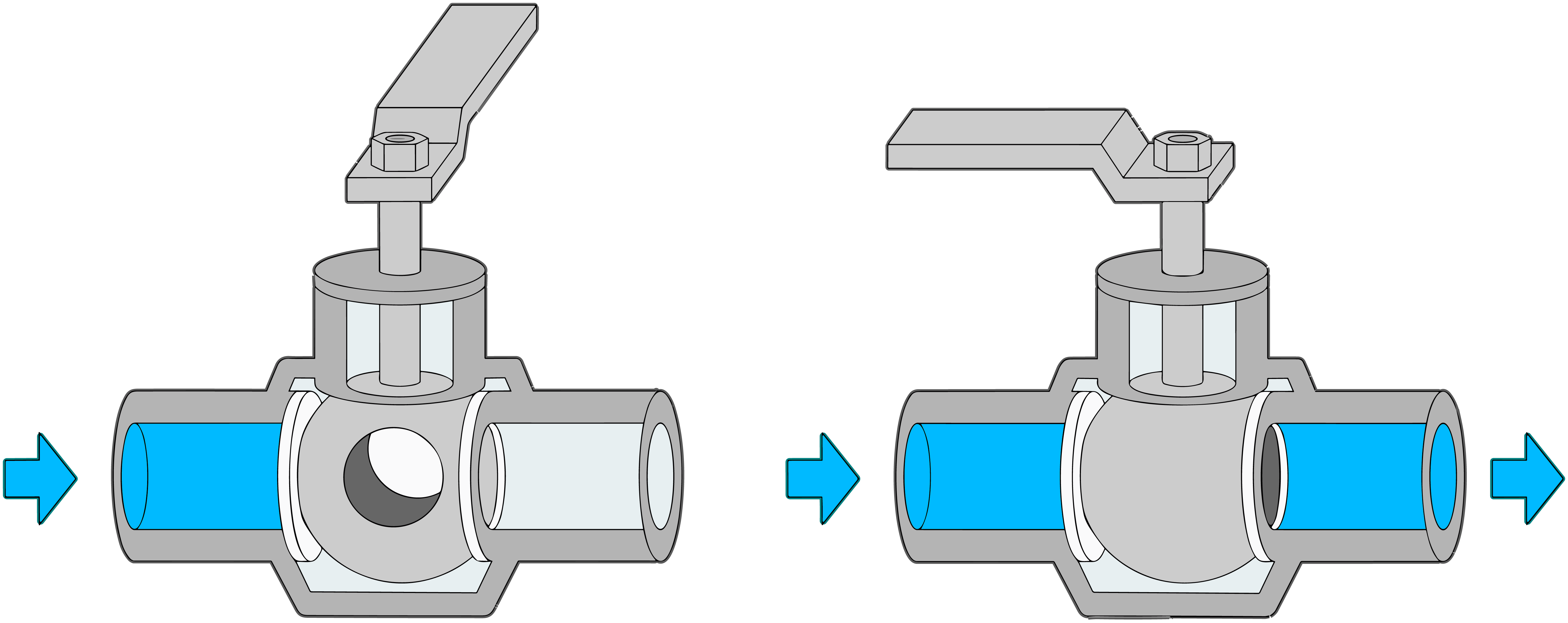
  • Ball valves have a central ball with a hole or bore.
  • Positioned in a valve casing, they have entry and exit ports for liquids or gases.
  • The ball connects to a stem, which is the external control point.

HOW THEY WORK :

  • The essence of a ball valve is its rotation.
  • Open: The ball’s bore matches the ports, allowing flow.
  • Closed: The ball turns 90 degrees, blocking the ports and sealing off the flow.

Ball valve

OPERATING BALL VALVES :

  • Opening: Rotate the handle or actuator 90 degrees in the pipeline’s direction, aligning the bore for fluid passage.
  • Closing: Rotate back 90 degrees, making the bore perpendicular and sealing off the flow.

WHY USE BALL VALVES ?

  • Speed: Their quarter-turn mechanism ensures swift operation.
  • Durability: They have a long lifespan with minimal upkeep.
  • Leakage Prevention: They seal tightly when closed.
  • Flexibility: Suitable for various tasks like flow control, throttling, and flow diversion.
  • Automation Compatibility: Easily paired with automated systems for remote control.

WHERE ARE BALL VALVES USED ?

  • Oil and Gas: For pipelines, refineries, and petrochemical applications.
  • Water Systems: In supply networks, treatment plants, and irrigation setups.
  • Chemical Handling: For various chemicals in processing facilities.
  • Temperature Control: In HVAC systems for water flow regulation.
  • Food Processing: Used due to their clean and hygienic design.

CONCLUSION :

Ball valves are pivotal in fluid management, with their ease of operation and reliable sealing. Grasping their functionality helps professionals choose them for maximum efficiency in fluid systems. From oil and gas to food processing, ball valves remain instrumental in fluid control.