Valves in Natural Gas Pressure Reduction Stations: Types, Features, and Selection Criteria
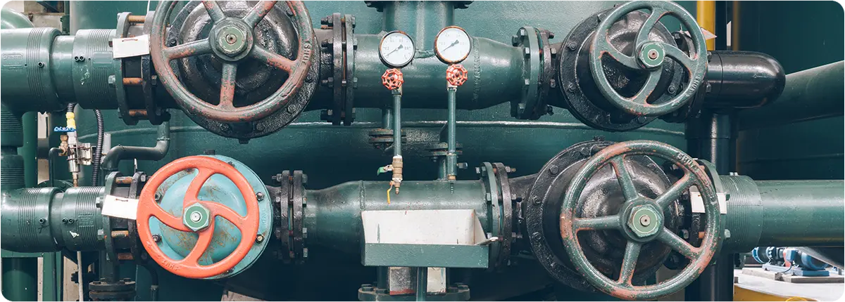
In high-pressure transmission pipelines, natural gas typically flows at 40–70 bar. However, city networks and industrial facilities require the gas at much lower pressures, usually between 1–20 bar. This adjustment is achieved in pressure reduction stations (PRS). Within these stations, valves play a critical role, not only in reducing pressure but also in ensuring operational safety, efficiency, and continuity.
KEY TYPES OF VALVES IN PRESSURE REDUCTION STATIONS
Pressure Reducing Valves (PRVs)
- The primary element of PRS, designed to reduce high inlet pressure to a stable and safe outlet pressure.
- Features:
- Precise control of downstream pressure
- Noise and cavitation reduction options
- Compatible with automation and control systems
- Standards: EN 334, ISO 23555
By-Pass Valves
- Provide redundancy in case of regulator failure or during maintenance.
- Example: Critical installations often employ dual regulators plus a by-pass line to guarantee uninterrupted supply.
Blowdown / Drain Valves
- Used to depressurize or empty sections of the pipeline.
- Function: Ensures maintenance safety by isolating sections under pressure.
Safety and Relief Valves
- Protect the system against unexpected overpressure conditions.
- Working principle: Opens automatically at a preset pressure to release excess gas.
Control Valves
- Integrated into SCADA and PLC systems for continuous monitoring.
- Adjust flow, pressure, and temperature parameters dynamically.
- Essential in industrial city gate stations with high consumption levels.
VALVE SELECTION CONSIDERATIONS
Flow Range and Capacity
Valves must cover both minimum and maximum consumption scenarios.
- Example: For a PRS with a design flow of 5,000 Sm³/h, the pressure reducing valve should reliably handle flows between 2,000–7,000 Sm³/h.
Pressure Drop (ΔP)
Pressure reduction is the core task of PRS valves.
ΔP = Pin − Pout
- Pin: Inlet pressure (bar)
- Pout: Outlet pressure (bar)
Engineering Note: Rapid fluctuations in outlet pressure can trigger cavitation and noise problems.
Control Characteristics
- Linear: Flow increases proportionally with valve opening.
- Equal Percentage: Provides stable control at low openings and rapid flow increase at higher openings.
- Quick Opening: Best suited for emergency shutoff or rapid actuation.
Cavitation and Noise Control
- High-pressure drops can cause cavitation inside the valve body.
- Solution: Multi-stage pressure-reducing valves or silencers.
Actuator Type
- Pneumatic Actuators: Fast response, most common in PRS.
- Electric Actuators: Strong integration with SCADA but slower response.
- Hydraulic Actuators: Used in extra-large valve sizes.
SAFETY AND STANDARDS
- EN 334 – Gas pressure regulators
- ISO 23555 – Industrial gas pressure regulation
- PED (Pressure Equipment Directive) – EU pressure equipment directive
- ASME – Pressure ratings and design standards
REAL-WORLD APPLICATIONS
- Istanbul City Gate Stations (Turkey): High-capacity PRVs reduce gas pressure from 70 bar to 19 bar for city distribution.
- Ruhr Region (Germany): Dual regulators with by-pass valves provide 100% redundancy for enhanced reliability.
- Japan: Multi-stage noise-reducing valves are installed in urban PRS located near residential areas.
CONCLUSION
Valves in pressure reduction stations are fundamental to safe, efficient, and uninterrupted natural gas distribution. Selection must consider flow ranges, pressure drops, cavitation risk, and automation requirements. Modern PRS increasingly rely on SCADA integration, advanced regulators, and multi-stage valve designs to ensure both operational efficiency and safety. Choosing the right valve technology is not just a matter of performance—it is a cornerstone of reliable and sustainable gas supply.
 Convalve
 Convalve