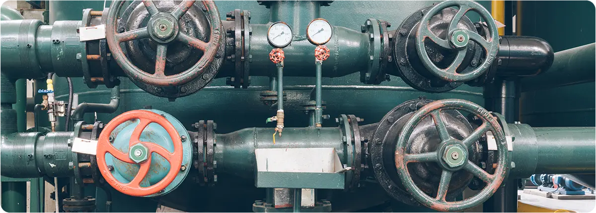
In industrial process automation, monitoring and controlling liquid levels is essential for both operational safety and efficiency. Level gauges and controllers play a critical role in ensuring accurate measurement, preventing overflow, protecting pumps from dry running, and maintaining stable process conditions. Depending on the industry—whether it is chemical, oil and gas, food and beverage, power generation, or water treatment—different types of level gauges and controllers are deployed to suit specific operational requirements.
TYPES OF LEVEL GAUGES
- Sight Glass Level Gauges
- A transparent tube or glass window that shows the actual liquid level inside a tank.
- Advantages: Direct reading, simple construction, reliable for non-hazardous fluids.
- Limitations: Not suitable for high-pressure, high-temperature, or corrosive media.
- Magnetic Level Gauges
- Operate on the principle of magnetic coupling, using a float containing a magnet that moves with the liquid level.
- The position of the float is tracked by an external indicator or sensor.
- Benefits: Safe for high-pressure and high-temperature applications, can be combined with switches and transmitters for automation.
- Reflex and Transparent Gauges
- Designed for high-pressure steam or chemical service.
- Reflex gauges use prism glass to enhance the visibility of the liquid column.
- Transparent gauges allow the use of backlighting to improve readability.
LEVEL CONTROLLERS
Level controllers ensure automatic regulation of liquid levels in tanks or vessels. They are often integrated with transmitters, relays, and actuators to maintain process stability.
- On/Off Controllers: Trigger pumps, solenoid valves, or alarms when the level reaches a set point.
- Proportional Controllers: Adjust the flow of inlet or outlet valves gradually, maintaining stable liquid levels.
- Smart Controllers: Equipped with microprocessors, enabling digital communication, diagnostics, and predictive maintenance.
KEY ENGINEERING CONSIDERATIONS
When selecting and designing level gauges and controllers, several parameters should be evaluated:
- Process Conditions
- Temperature (°C or °F)
- Pressure (bar or psi)
- Chemical compatibility with gauge materials
- Accuracy and Range
- For critical applications such as dosing, an accuracy of ±0.25% may be required.
- Range should be chosen according to vessel dimensions.
- Safety Standards
- Compliance with ASME, API, or IEC standards depending on industry.
- Explosion-proof and flameproof designs for hazardous areas.
- Maintenance and Reliability
- Magnetic level gauges and smart controllers reduce downtime through self-diagnostics.
- Corrosion-resistant materials (e.g., stainless steel 316L, Hastelloy) ensure durability.
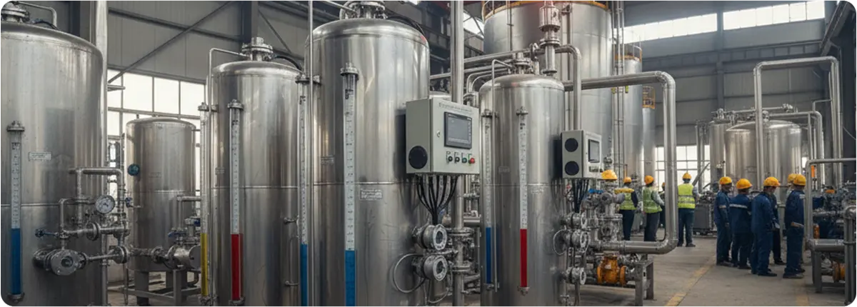
EXAMPLE APPLICATION IN WATER TREATMENT PLANT
Consider a clarifier tank in a municipal water treatment facility:
- Magnetic level gauge provides continuous monitoring.
- Level switch integrated with the controller prevents overflow by activating pumps when the tank is nearly full.
- Smart level controller communicates with the SCADA system, optimizing pump cycles and saving energy.
ADVANTAGES OF USING LEVEL GAUGES & CONTROLLERS
- Operational Safety: Prevents overflow, leakage, or pump cavitation.
- Process Optimization: Maintains consistent product quality.
- Energy Efficiency: Intelligent control reduces unnecessary pumping cycles.
- Versatility: Applicable across multiple industries and for various types of fluids.
CONCLUSION
Level gauges and controllers are indispensable components of process automation systems. From simple sight glasses to advanced magnetic and electronic controllers, these instruments safeguard processes, improve efficiency, and reduce operational costs. Careful selection based on process requirements, material compatibility, and safety standards ensures reliable and long-lasting performance.