Valve test standards translate “quality” into measurable acceptance criteria. They define:

  • What to test (shell, seat, backseat, operational/functional, fire-safe, emissions, cryogenic, high-pressure gas, etc.)
  • How to test (media, pressure levels, duration, sequences)
  • What’s acceptable (leakage categories/classes, visual vs. measured rates)
  • Documentation (traceability, certificates, stamping/marking)

Choosing (and specifying) the right standard prevents disputes, makes FATs/SATs predictable, and ensures consistent field performance.
Maintenance

CORE STANDARDS “MAP”

Below is the practical landscape most plants and EPCs navigate:

  • General industrial isolation valves (metal/soft seat)
    • API 598 (North America)
    • ISO 5208 (International)
    • EN 12266-1/-2 (Europe)
    • ASME B16.34
  • Pipeline valves
    • API 6D / ISO 14313
    • API 6DSS / ISO 14723
  • Control valves
    • IEC 60534-4
    • FCI/ANSI 70-2
  • Waterworks valves
    • AWWA (C509, C515, C504, C507, etc.)
  • Fire-safe and safety-critical
    • API 607 / ISO 10497
    • API 6FA
  • Fugitive emissions (FE)
    • ISO 15848-1
    • API 641
  • Cryogenic services
    • BS 6364 and ISO 28921

API 598 VS. ISO 5208 VS. EN 12266-1

  • API 598: zero visible leakage for soft seats; limited for metal seats.
  • ISO 5208: Leakage Rates A–H; Rate A ≈ hermetic.
  • EN 12266-1: aligns closely with ISO 5208, adds EU-specific sequences.

PIPELINE VALVES: API 6D / ISO 14313

Adds DBB/DIB validation, cavity relief, operational torque, and pneumatic tightness for gas service. Stricter than API 598.

CONTROL VALVE LEAKAGE

Defined by IEC 60534-4 and FCI 70-2. Leakage Classes II–VI range from moderate shutoff to bubble-tight.

FIRE-SAFE STANDARDS

API 607, ISO 10497, and API 6FA: expose a pressurized valve to fire, then quench, ensuring containment.

FUGITIVE EMISSIONS

ISO 15848-1 quantifies stem leakage under cycles. API 641 focuses on quarter-turn valves.

CRYOGENIC

BS 6364 and ISO 28921: test at cryogenic temperatures, check sealing, torque, and leakage under cold soak and warm-up.

WATERWORKS

AWWA standards (C509, C515, C504, C507) emphasize hydrostatic proof, seat leakage, coating integrity, torque.

TEST METHODS ON FATs

Hydrostatic shell test, hydrostatic seat test, low-pressure air/gas seat test, backseat test, functional/operational tests, specialty tests (fire-safe, FE, cryogenic, etc.).

SPECIFICATIONS THAT PREVENT HEADACHES

  • API 598 for isolation valves
  • API 6D for pipeline valves
  • FCI 70-2 Class IV for control valves
  • API 607 for fire-safe
  • ISO 15848-1 Class A for emissions
  • BS 6364 for cryogenic

DOCUMENTATION & QA YOU SHOULD REQUEST

Mill certificates, calibrated test equipment, test records, valve ID, special certificates (fire-safe, FE, cryogenic).

SERIES PLAN

Part 2 – API/ASME/FCI deep dive
Part 3 – ISO/EN stack
Part 4 – Waterworks
Part 5 – Project spec templates.
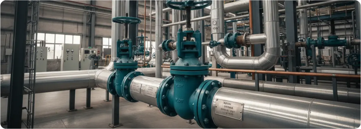
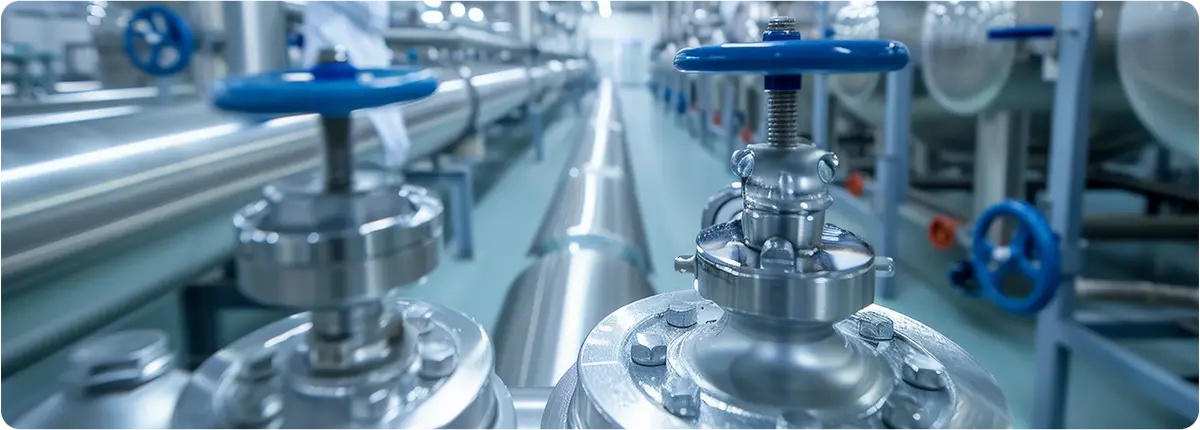
In industrial fluid handling systems, valve selection plays a crucial role in ensuring process efficiency, safety, and reliability. Among the wide variety of valve designs, plug valves stand out for their simple quarter-turn mechanism, compact design, and ability to provide tight shut-off. Their versatility makes them a popular choice across industries such as oil and gas, chemical processing, wastewater treatment, and power generation.

Plug Valves

DESIGN AND WORKING PRINCIPLE

A plug valve consists of a cylindrical or tapered plug housed inside a valve body. The plug contains a through-hole (port) that allows fluid to pass through when aligned with the flow path. By rotating the plug 90 degrees, the flow is either fully opened or completely shut off.

Key design elements include:

  • Valve body: Typically made of cast steel, stainless steel, or ductile iron.
  • Plug: Cylindrical or conical, with one or more ports.
  • Sealing mechanism: Can be lubricated (using sealant) or non-lubricated (using sleeve or elastomer liners).
  • Actuation: Operated manually (lever or gear), pneumatically, hydraulically, or electrically.

TYPES OF PLUG VALVES

  • Lubricated Plug Valves: Use sealant injected around the plug to reduce friction and improve sealing. Common in oil & gas pipelines.
  • Non-Lubricated Plug Valves: Use PTFE or elastomer sleeves for low-maintenance operation. Popular in chemical and food processing.
  • Eccentric Plug Valves: Feature an off-centered plug for better sealing and lower torque. Used widely in wastewater systems.
  • Expanding Plug Valves: Mechanically expand during operation for bubble-tight sealing. Ideal for critical isolation services.
  • Multi-Port Plug Valves: Enable multiple flow paths for redirection between pipelines. Common in chemical and batch process applications.

APPLICATIONS OF PLUG VALVES

  • Oil & Gas: Upstream and downstream pipeline control.
  • Chemical Processing: Resistant to corrosion; often made from stainless steel or lined bodies.
  • Water/Wastewater: Eccentric plug valves used in treatment and distribution systems.
  • Power Generation: Cooling water, condensate, and auxiliary systems.
  • Food & Beverage: Non-lubricated hygienic designs prevent product contamination.

ADVANTAGES OF PLUG VALVES

  • Quick operation with quarter-turn mechanism
  • Compact and simple construction
  • Handles slurry and viscous fluids effectively
  • Available in multi-port configurations
  • Reliable sealing in high-pressure service
  • Durable under extreme temperature conditions

LIMITATIONS

  • High torque required for large diameters
  • Not ideal for throttling applications
  • Lubricated designs need periodic maintenance
  • Higher pressure drop compared to ball valves

SELECTION CRITERIA

  • Media Type: Corrosive, slurry, or clean fluids.
  • Pressure/Temperature: High pressure favors lubricated or expanding types.
  • Actuation: Manual for small valves; pneumatic or electric for automation.
  • Maintenance: Non-lubricated = lower maintenance, lubricated = longer service life.
  • Flow Path: Multi-port types reduce the need for multiple valves.

ENGINEERING NOTES

Flow Coefficient (Cv) is generally lower than ball valves due to internal restrictions. The pressure drop (ΔP) can be estimated using:

ΔP = Q² / (Cv² × SG)

Where Q = flow rate (gpm), and SG = specific gravity. Torque varies based on valve size, sealing type, and medium; actuator sizing must account for torque demand.

COMPARISON TABLE

Feature Plug Valves Ball Valves Gate Valves
Operation Quarter-turn Quarter-turn Multi-turn
Sealing Good to bubble-tight Excellent shut-off Moderate
Throttling Limited Limited Fair
Maintenance Medium Low Medium
Applications Oil & gas, wastewater General process, utilities Pipeline isolation

CONCLUSION

Plug valves are reliable, versatile, and efficient solutions for quick shut-off and flow control applications. Their various configurations — including lubricated, non-lubricated, eccentric, expanding, and multi-port types — make them adaptable to diverse industrial needs. With proper selection and maintenance, plug valves provide long-term performance, minimize downtime, and optimize operational cost efficiency.

The dairy industry is one of the most demanding sectors in terms of hygiene, efficiency, and reliability. Every step of milk processing — from collection and pasteurization to the production of cheese, yogurt, butter, and other dairy products — relies heavily on fluid handling systems. Among these, valves play a critical role in ensuring safe product flow, hygienic processing, and system reliability.

Valves not only control the direction, pressure, and flow of liquids but also protect against contamination, mixing of incompatible products, and potential equipment damage. Choosing the right valve is therefore crucial for maintaining product quality, food safety compliance, and plant productivity.

Valves Used in the Dairy Industry

COMMON TYPES OF VALVES IN THE DAIRY INDUSTRY

  • Butterfly Valves: Compact, lightweight, cost-effective, and easy to clean. Used in milk transfer pipelines, yogurt lines, and low- to medium-pressure processes. Polished stainless steel and FDA-approved seals ensure hygiene.
  • Ball Valves: Provide quick shut-off and full bore flow. Suitable for cream transfer and CIP (Clean-in-Place) circuits. Special sanitary designs prevent cleaning issues.
  • Diaphragm Valves: Ideal for aseptic processes with flexible diaphragm sealing. Common in fermentation tanks and probiotic milk processing lines.
  • Mix-Proof (Double Seat) Valves: Allow two different fluids to flow without mixing. Essential in multi-product pipelines handling milk, whey, and cleaning agents alternately.
  • Check Valves: Prevent reverse flow, ensuring pump and process protection.
  • Safety Valves: Protect systems from overpressure in pasteurizers, CIP tanks, and storage vessels.

MATERIAL SELECTION AND HYGIENIC STANDARDS

Since dairy valves come into direct contact with food products, material selection is vital. Stainless Steel 316L is preferred for its corrosion resistance and durability against cleaning chemicals. Sealing materials include EPDM, FKM, or PTFE. Surface finishes should meet ≤ Ra 0.8 µm to ensure hygiene compliance.

Key Standards:

  • FDA – Material compliance for food safety.
  • 3-A Sanitary Standards – Hygienic design for dairy equipment.
  • EHEDG – Certification for hygienic processing equipment.

APPLICATION EXAMPLES IN DAIRY PROCESSING

Process Step Preferred Valve Types Key Considerations
Milk reception Butterfly valves, check valves Easy operation, prevent backflow
Pasteurization Mix-proof, diaphragm valves Aseptic conditions, temperature resistance
Yogurt & cheese making Diaphragm, mix-proof valves Hygienic separation of product and CIP
CIP/SIP cleaning Ball valves, butterfly valves Leak-free design, chemical compatibility
Storage tanks Safety valves, level control Pressure relief, product safety

AUTOMATION AND SMART VALVE CONTROL

Modern dairy plants integrate valves with pneumatic or electric actuators for remote operation. Valve control heads provide position feedback, while PLC/SCADA systems enable automated cleaning cycles, routing, and monitoring. Automation boosts efficiency, safety, and traceability in large-scale production.

SELECTION CRITERIA FOR DAIRY VALVES

  • Hygiene compliance (FDA, EHEDG, 3-A certifications)
  • Cleanability (CIP/SIP compatibility, no dead zones)
  • Durability (chemical and temperature resistance)
  • Flow requirements (full bore vs. throttling)
  • Automation needs (manual vs. actuated)
  • Cost vs. lifecycle performance

CONCLUSION

Valves are essential in the dairy industry, influencing hygiene, product quality, and operational efficiency. Selecting the right valve type — whether butterfly, ball, diaphragm, mix-proof, or safety — ensures smooth production and compliance with international food safety standards. As automation and digitalization advance, valves evolve into smart, integrated components that enhance sustainability, efficiency, and reliability.

Knife gate valves are a specialized type of shut-off valve designed to handle fluids with suspended solids, slurries, or fibrous materials. Unlike standard gate valves, which use a wedge-shaped gate, knife gate valves use a thin, sharp-edged blade that can cut through thick media, making them indispensable in industries such as wastewater treatment, mining, pulp & paper, and chemical processing.

Knife Gate Valves

WORKING PRINCIPLE

The core principle of a knife gate valve is simple yet effective. When actuated, a flat blade (the ‘knife’) slides down into the valve seat, cutting through the media and forming a tight seal. In the open position, the blade retracts completely, allowing for a nearly unobstructed flow path.

  • Open position: Full-bore flow with minimal pressure drop.
  • Closed position: The knife-shaped disc cuts through solids, providing reliable shutoff.

DESIGN FEATURES

Knife gate valves are built for durability in harsh operating environments:

  • Body construction: Typically cast iron, ductile iron, carbon steel, or stainless steel.
  • Gate design: Sharp-edged stainless steel blade to shear through solids.
  • Seat options: Soft seats (elastomer, PTFE) for tight shutoff, or metal seats for high-temperature/abrasive applications.
  • Actuation: Manual (handwheel), pneumatic, hydraulic, or electric actuators.
  • Sizes & ratings: DN 50–DN 1200, usually up to PN 10 or ANSI Class 150.

APPLICATIONS

  • Wastewater treatment plants: Managing sludge and thick waste streams.
  • Mining industry: Controlling abrasive slurries of ore, sand, and tailings.
  • Pulp & paper mills: Handling fibrous pulp mixtures.
  • Chemical industry: Managing corrosive fluids with solid particles.
  • Food industry: Processing thick pastes, starches, or viscous ingredients.

ADVANTAGES

  • Cuts through solids and fibrous materials.
  • Compact design with minimal space requirements.
  • Low-pressure drop when fully open.
  • Cost-effective for large-diameter pipelines.
  • Easy to maintain with replaceable seats and seals.

LIMITATIONS

  • Not suitable for high-pressure applications above PN 10.
  • Slower operation compared to quarter-turn valves.
  • Not ideal for throttling; mainly on/off service.
  • Seat wear with abrasive slurries requires maintenance.

SELECTION CRITERIA

Factors to consider:

  1. Media characteristics: solids, abrasiveness, chemical composition.
  2. Pressure and temperature ratings.
  3. Actuation method: manual vs. automated.
  4. Sealing requirements: soft seats vs. metal seats.
  5. Installation space: vertical installation recommended.

COMPARISON WITH STANDARD GATE VALVES

  • Knife gate valve: Designed for slurry and solids, sharper disc, low-pressure ratings.
  • Standard gate valve: Designed for clean liquids and gases, higher pressure ratings, wedge-shaped gate.

ENGINEERING NOTES

The flow coefficient (Cv) of a knife gate valve is relatively high in the fully open position:

Q = Cv * sqrt(ΔP / SG)

  • Q = Flow rate (GPM)
  • Cv = Valve flow coefficient
  • ΔP = Pressure drop (psi)
  • SG = Specific gravity of fluid

Recommended slurry velocity: 1.5–3.5 m/s.

CONCLUSION

Knife gate valves play a vital role in industries dealing with challenging fluids. Their unique design enables them to handle slurries, viscous materials, and fibrous suspensions effectively. Proper selection ensures reliable operation, safety, and long service life.

Diaphragm valves are versatile flow control devices widely used in industries that demand high levels of cleanliness, corrosion resistance, and precise regulation. Unlike other valve types, diaphragm valves utilize a flexible diaphragm that comes into contact with the valve seat to regulate or shut off fluid flow. This unique design eliminates many of the leakage and contamination risks present in traditional valve types, making diaphragm valves a popular choice in pharmaceuticals, food and beverage, chemical processing, and water treatment applications.

Diaphragm Valves

DESIGN AND WORKING PRINCIPLE

A diaphragm valve consists of three main components: the valve body, the flexible diaphragm, and the actuator or bonnet assembly. The valve body is typically made from corrosion-resistant materials such as stainless steel, PVC, or glass-lined metals. The diaphragm, made from elastomers such as EPDM, PTFE, or rubber, serves as the sealing element. The actuator applies mechanical or pneumatic force to move the diaphragm against the valve seat.

When the diaphragm is pressed against the seat, it seals the flow path completely. When lifted, fluid passes freely through the valve body. Since the diaphragm isolates the fluid from the moving parts, contamination risks are minimized — a key advantage in hygienic applications.

TYPES OF DIAPHRAGM VALVES

There are two primary designs of diaphragm valves: weir-type and straight-through. The weir-type features a raised lip that aids throttling and control applications, while the straight-through type offers minimal flow resistance and is ideal for viscous or slurry fluids. Diaphragm valves may also be manual or actuated (electric, pneumatic, or hydraulic), depending on process automation needs.

ADVANTAGES OF DIAPHRAGM VALVES

  • Leak-proof sealing eliminates external leakage.
  • High corrosion resistance suitable for aggressive chemicals.
  • Clean operation ideal for sanitary applications.
  • Handles liquids, gases, and slurries effectively.
  • Simple design allows low maintenance and reliability.

LIMITATIONS

  • Not suitable for very high-temperature applications.
  • Limited pressure handling capacity.
  • Diaphragm material requires periodic replacement.

INDUSTRIAL APPLICATIONS

Diaphragm valves are used across various sectors including:

  • Pharmaceutical and biotechnology processes in sterile environments.
  • Food and beverage production requiring hygienic handling.
  • Chemical processing with corrosive or hazardous media.
  • Water and wastewater treatment plants.
  • Mining and cement industries handling abrasive slurries.

SELECTION CRITERIA

  • Fluid type and chemical properties.
  • Operating temperature and pressure range.
  • Material compatibility for both valve body and diaphragm.
  • Connection type (flanged, threaded, welded).
  • Automation and control requirements.

MAINTENANCE CONSIDERATIONS

  • Regular diaphragm inspection for cracks and wear.
  • Correct torque application to prevent sealing damage.
  • Periodic replacement based on service hours.
  • Sanitary cleaning protocols for regulated industries.

CONCLUSION

Diaphragm valves combine cleanliness, corrosion resistance, and operational reliability, making them indispensable for industries such as pharmaceuticals, food, and chemical processing. Their leak-free design, ease of maintenance, and flexibility make them a trusted solution for safe and efficient flow control. Selecting the right materials and configuration ensures durability and process integrity.

In high-pressure transmission pipelines, natural gas typically flows at 40–70 bar. However, city networks and industrial facilities require the gas at much lower pressures, usually between 1–20 bar. This adjustment is achieved in pressure reduction stations (PRS). Within these stations, valves play a critical role, not only in reducing pressure but also in ensuring operational safety, efficiency, and continuity.

Valves Used in Pressure Reducing

KEY TYPES OF VALVES IN PRESSURE REDUCTION STATIONS

Pressure Reducing Valves (PRVs)

  • The primary element of PRS, designed to reduce high inlet pressure to a stable and safe outlet pressure.
  • Features:
    • Precise control of downstream pressure
    • Noise and cavitation reduction options
    • Compatible with automation and control systems
  • Standards: EN 334, ISO 23555

By-Pass Valves

  • Provide redundancy in case of regulator failure or during maintenance.
  • Example: Critical installations often employ dual regulators plus a by-pass line to guarantee uninterrupted supply.

Blowdown / Drain Valves

  • Used to depressurize or empty sections of the pipeline.
  • Function: Ensures maintenance safety by isolating sections under pressure.

Safety and Relief Valves

  • Protect the system against unexpected overpressure conditions.
  • Working principle: Opens automatically at a preset pressure to release excess gas.

Control Valves

  • Integrated into SCADA and PLC systems for continuous monitoring.
  • Adjust flow, pressure, and temperature parameters dynamically.
  • Essential in industrial city gate stations with high consumption levels.

VALVE SELECTION CONSIDERATIONS

Flow Range and Capacity

Valves must cover both minimum and maximum consumption scenarios.

  • Example: For a PRS with a design flow of 5,000 Sm³/h, the pressure reducing valve should reliably handle flows between 2,000–7,000 Sm³/h.

Pressure Drop (ΔP)

Pressure reduction is the core task of PRS valves.
ΔP = Pin − Pout

  • Pin: Inlet pressure (bar)
  • Pout: Outlet pressure (bar)

Engineering Note: Rapid fluctuations in outlet pressure can trigger cavitation and noise problems.

Control Characteristics

  • Linear: Flow increases proportionally with valve opening.
  • Equal Percentage: Provides stable control at low openings and rapid flow increase at higher openings.
  • Quick Opening: Best suited for emergency shutoff or rapid actuation.

Cavitation and Noise Control

  • High-pressure drops can cause cavitation inside the valve body.
  • Solution: Multi-stage pressure-reducing valves or silencers.

Actuator Type

  • Pneumatic Actuators: Fast response, most common in PRS.
  • Electric Actuators: Strong integration with SCADA but slower response.
  • Hydraulic Actuators: Used in extra-large valve sizes.

SAFETY AND STANDARDS

  • EN 334 – Gas pressure regulators
  • ISO 23555 – Industrial gas pressure regulation
  • PED (Pressure Equipment Directive) – EU pressure equipment directive
  • ASME – Pressure ratings and design standards

REAL-WORLD APPLICATIONS

  • Istanbul City Gate Stations (Turkey): High-capacity PRVs reduce gas pressure from 70 bar to 19 bar for city distribution.
  • Ruhr Region (Germany): Dual regulators with by-pass valves provide 100% redundancy for enhanced reliability.
  • Japan: Multi-stage noise-reducing valves are installed in urban PRS located near residential areas.

CONCLUSION

Valves in pressure reduction stations are fundamental to safe, efficient, and uninterrupted natural gas distribution. Selection must consider flow ranges, pressure drops, cavitation risk, and automation requirements. Modern PRS increasingly rely on SCADA integration, advanced regulators, and multi-stage valve designs to ensure both operational efficiency and safety. Choosing the right valve technology is not just a matter of performance—it is a cornerstone of reliable and sustainable gas supply.

In industrial process systems, piping materials are more than just conduits for transporting fluids. They directly influence system reliability, efficiency, safety, and long-term operating costs. While cost and mechanical strength are important, the most critical factor in selecting the right pipe material is the nature of the fluid being transported.

Improper material selection can lead to premature failures, corrosion, high maintenance costs, and even safety hazards. This article explores how fluid characteristics impact material selection, compares common pipe materials, and provides engineering insights to ensure long-lasting piping systems.

Right Product

HOW FLUID PROPERTIES AFFECT PIPE MATERIAL SELECTION

Each fluid has unique physical and chemical properties that determine material compatibility. The most influential factors are:

  • Temperature (T): Materials expand or weaken at elevated temperatures. A pipe must maintain strength and tightness across the entire operating range.
  • Pressure (P): Internal pressure resistance is defined by hoop stress, calculated as:
    σ = (P · D) / (2 · t)
    Where:
    σ = hoop stress (MPa)
    P = internal pressure (Pa or bar)
    D = pipe outside diameter (mm)
    t = wall thickness (mm)
  • Chemical compatibility: Acids, bases, solvents, and chlorinated media require corrosion-resistant materials.
  • Presence of solids: Fluids with abrasive particles accelerate erosion and shorten service life.
  • Viscosity & density: Higher viscosity fluids increase friction losses, requiring more pumping energy.

COMPARISON OF COMMON PIPING MATERIALS

The table below summarizes the advantages and limitations of frequently used piping materials:

Material Advantages Limitations Typical Applications
Carbon Steel High pressure resistance, low cost Prone to corrosion, heavy Steam lines, mechanical systems
Stainless Steel Excellent corrosion resistance, high temperature tolerance Expensive, harder to process Chemical, food, pharmaceutical plants
Copper Hygienic, easy to fabricate Poor resistance to acidic media, costly Potable water, HVAC
PVC Lightweight, inexpensive, easy to install Limited to low temperature/pressure Wastewater, drainage
CPVC Higher temperature and chemical resistance than PVC Limited in very high-pressure systems Chemical processing, hot water
HDPE Flexible, impact-resistant Susceptible to UV degradation Natural gas, water distribution

FLUID-PIPE INTERACTION: HYDRAULIC CONSIDERATIONS

Material choice also impacts hydraulic performance. Pressure drop across a system is often calculated using the Darcy–Weisbach equation:

ΔP = f · (L / D) · (ρv² / 2)

Where:
ΔP = pressure loss (Pa)
f = friction factor (from Moody chart)
L = pipe length (m)
D = pipe diameter (m)
ρ = fluid density (kg/m³)
v = fluid velocity (m/s)

Pipes with smoother surfaces (e.g., CPVC, HDPE) reduce friction losses compared to carbon steel, lowering pump energy requirements and overall operating costs.

CPVC VS. METAL PIPING SYSTEMS

In recent years, Chlorinated Polyvinyl Chloride (CPVC) has become a strong alternative to traditional metal pipes in chemical and water distribution systems.

  • Corrosion resistance: CPVC resists acids, bases, and chlorine-based chemicals, whereas carbon steel corrodes quickly.
  • Weight & installation: CPVC is lighter, easier to install, and requires simple solvent cementing rather than welding.
  • Thermal resistance: CPVC is safe up to 95–100 °C, while stainless steel withstands higher temperatures.
  • Cost: CPVC offers a lower total installed cost compared to stainless steel.

This makes CPVC an attractive option for industries prioritizing both performance and cost efficiency.

IMPACT ON MAINTENANCE AND OPERATING COSTS

Poor material selection leads to:

  • Frequent maintenance and unscheduled downtime
  • Higher pumping energy due to increased friction losses
  • Premature replacement of corroded or eroded pipelines
  • Greater total cost of ownership (TCO)

Conversely, choosing the right material extends service life, reduces operating costs, and ensures system safety and compliance.

CONCLUSION

Piping material selection should not be based solely on initial purchase cost. Fluid characteristics—temperature, pressure, chemistry, and particulate content—are the most critical factors. By carefully evaluating these parameters and comparing material performance, engineers can design piping systems that are safe, durable, and cost-effective.

Modern solutions like CPVC demonstrate that alternative materials can often outperform metals in terms of longevity, chemical resistance, and lifecycle cost savings.

In industrial fluid control systems, actuators play a vital role in the operation of butterfly valves. The right actuator ensures faster opening and closing cycles, allows for precise and incremental flow regulation, and ultimately improves overall system efficiency. By delivering the necessary torque, actuators make it possible to operate valves reliably, safely, and in a way that supports continuous operations.

Below is an overview of the main actuator types used in industrial butterfly valves, along with their applications and important selection factors.

Dogru Ürün Seçimi

MANUAL ACTUATORS

Manual actuators are the simplest type, operated using a handwheel, lever, or crank. They require no external power source and are ideal for systems where access is easy and automation is not necessary.

For larger butterfly valves, gear mechanisms are often used to increase torque, and advanced models may include analog position indicators for the valve disc.

  • Pros: Low cost, simple design, easy maintenance
  • Cons: Suitable only for smaller valves, slow actuation speed, limited use in critical pipelines

ELECTRIC ACTUATORS

Electric actuators use a bidirectional motor to open and close valves remotely. Integrated gearboxes reduce motor speed and increase torque output. These actuators are generally low-maintenance, energy-efficient, and operate quietly, making them suitable for process control in light-duty or non-critical applications.

Many electric actuators are equipped with limit switches to automatically stop the motor when the valve is fully open or closed.

  • Pros: Remote operation, quiet and clean operation, low power consumption
  • Cons: Requires a stable power supply, limited torque for heavy-duty applications

PNEUMATIC ACTUATORS

Pneumatic actuators operate using compressed air and can be single-acting (spring return) or double-acting. When air enters the actuator chamber, it moves a piston or plunger, producing linear or rotary motion that turns the valve disc.

These actuators are compact, lightweight, cost-effective, and provide rapid response times. They are widely used in frequently cycled pipelines such as gas distribution, steam lines, and slurry transport.

  • Pros: Fast actuation, lightweight, cost-efficient
  • Cons: Requires a dedicated compressed air supply

HYDRAULIC ACTUATORS

Hydraulic actuators are designed for large-diameter or high-pressure pipelines where high torque is essential. They operate using hydraulic oil or, in some cases, water. Available in both single-acting (spring return) and double-acting designs, hydraulic actuators can handle the most demanding industrial valve applications.

  • Pros: High torque capability, suitable for heavy-duty service
  • Cons: More complex maintenance, requires fluid management and leak prevention

FIVE KEY FACTORS TO CONSIDER WHEN CHOOSING A BUTTERFLY VALVE ACTUATOR

  • Duty Cycle: Indicates how frequently an actuator can operate before overheating or wearing out. Hydraulic actuators can operate with nearly a 100% duty cycle, ideal for high-frequency, high-pressure systems. Electric actuators may have lower duty cycles, around 25%, for intermittent operation.
  • Actuation Speed: Fast-acting actuators (hydraulic or pneumatic) are preferred for critical operations. Slow-operating actuators may be better for processes requiring gradual valve movement.
  • Process Media Characteristics: The type of fluid being handled—whether corrosive, toxic, or gaseous—determines actuator material requirements. The actuator housing should be as robust as or more durable than the valve body.
  • Safety and Redundancy: Fail-safe features, such as spring-return mechanisms, are essential in critical systems. For example, a fail-open hydraulic butterfly valve ensures the line remains uncontaminated in case of actuator failure.
  • Cost and Maintenance: Total cost includes purchase price, maintenance, and spare parts. Pneumatic actuators generally have longer service lives but require additional equipment like air compressors.

CONCLUSION

Choosing the right actuator for butterfly valves directly affects system performance, operational safety, and maintenance costs. Matching the actuator to system demands, fluid characteristics, and budget constraints ensures reliable operation, reduces downtime, and improves overall process efficiency.

In manufacturing and processing plants, complex systems often transport liquids, gases, or semi-solid slurries. To ensure these fluids move safely, efficiently, and without interruptions, the correct valves must be selected. A valve’s role in controlling pressure, flow rate, and direction directly affects process safety, operational efficiency, and equipment longevity.

An improperly selected valve can cause leaks, process inefficiencies, environmental hazards, and even serious workplace accidents. Choosing the right valve is not just a technical decision — it’s a strategic safety measure.

Below are critical factors every engineer and plant manager should evaluate when selecting industrial valves:

Right Product

LINE PRESSURE

Not all fluid systems operate under the same pressure. For example, a high-pressure steam pipeline is vastly different from a low-pressure cooling water loop.

Line pressure refers to the force exerted across the valve body by the fluid.

  • Exceeding design pressure limits can damage seals, cause leaks, and compromise valve integrity.
  • Pressure drops across the valve should be minimized to avoid process inefficiencies. For constant-pressure applications, gate valves are preferred due to their low pressure loss, whereas globe valves are used where precise flow regulation is required.

Special cases:

  • Safety Relief Valves (SRV): The set pressure must be carefully determined to ensure safe system pressure release.
  • Check Valves: The cracking pressure — the minimum pressure at which the valve allows flow — should match process requirements.

FLOW RATE AND CONTROL

Different valve designs manage fluid movement in distinct ways. Understanding the purpose of the valve is essential:

  • Will it simply start/stop flow?
  • Will it precisely regulate flow rate?
  • Will it change flow direction?

On/Off Applications:

  • Ball Valves: Fast operation, low pressure loss, excellent sealing.
  • Gate Valves: Slower actuation, better for reducing water hammer.
  • Butterfly Valves: Lightweight, compact, and quick to operate.

Precise Flow Control:

  • Needle Valves: Ideal for gas calibration or low-flow liquids.
  • V-Port Ball Valves: Provide linear control with low pressure drop.
  • Globe Valves: Allow gradual adjustments and different flow configurations.

Directional Control:

  • Check Valves: Allow flow in one direction only.
  • Multi-Port Valves (e.g., 3-way ball valves): Redirect flow between multiple lines.

TEMPERATURE RESISTANCE

Temperature affects both the medium flowing through the valve and the valve components themselves. High temperatures can cause expansion and seal deformation, while low temperatures can make materials brittle.

Material selection is critical:

  • Stainless Steel: Suitable for many applications up to 200–400 °C.
  • Nickel Alloys: Excellent for high-temperature and corrosive conditions.
  • PTFE (Teflon) Seats: Wide temperature range tolerance.
  • EPDM Rubber Seats: Good for moderate temperatures but limited in extreme heat.

Valves are categorized by temperature class according to standards and materials used. For cryogenic or extremely high-temperature applications, special designs are required.

BUDGET AND TOTAL COST OF OWNERSHIP

The real cost of a valve includes purchase price, installation, maintenance, and downtime costs.

Factors affecting cost:

  • Simpler designs (e.g., gate valves) are often cheaper but may not provide the best sealing.
  • Adding automation (actuators) increases upfront cost but improves long-term efficiency and reduces human error.
  • Hydraulic Actuators: High force and fast operation for large valves, but more complex maintenance.
  • Pneumatic Actuators: Safe for hazardous environments, but less precise.
  • Electric Actuators: Compact and cost-effective, suitable when slower operation is acceptable.

MATCHING VALVE TYPE AND MATERIAL TO THE APPLICATION

Choosing the right valve type is only part of the decision. The fluid’s chemical properties, toxicity, and corrosiveness determine the most suitable materials for both the valve body and sealing components. Extreme temperature or pressure ranges will further narrow down the choices.

CONCLUSION: SAFE AND EFFICIENT OPERATIONS DEPEND ON THE RIGHT VALVE

In industrial operations, valve selection is directly linked to safety, efficiency, and cost optimization. By carefully evaluating line pressure, flow control, temperature resistance, and budget, companies can ensure safer processes, lower maintenance costs, and longer equipment life.

For critical applications, always work with valve specialists and follow relevant industry standards to achieve optimal sizing, performance, and reliability.