Reverse flow in piping systems can trigger water hammer, cavitation, leaks, and even catastrophic equipment damage. The root causes are usually pressure fluctuations or sudden changes in flow direction. By combining the right check valve design, proper hydraulic analysis, and advanced control strategies, operators can minimize the risks associated with reverse flow.
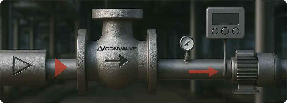
Valve Selection, and Control Strategies

THE RISKS OF REVERSE FLOW

Water Hammer: When flow is abruptly stopped or reversed, shock waves travel through the pipeline. These pressure spikes stress welds, seals, and supports, often resulting in loud vibration and mechanical failure.

Cavitation: Local pressure drops below vapor pressure, creating vapor bubbles. Their collapse in high-pressure zones leads to pitting, seal wear, and pump impeller erosion.

Valve Slam and Leakage: Swing check valves are prone to slamming against the seat during backflow events, accelerating wear and increasing the chance of fugitive emissions.

Overpressure and Contamination: Repeated reverse flow generates high-frequency pressure surges. These can exceed design limits, damage fittings, and increase contamination risks in potable water or chemical pipelines.

HYDRAULIC FUNDAMENTALS: QUANTIFYING THE IMPACT

Joukowsky Equation (water hammer pressure rise):
ΔP = ρ · a · Δv

Where:
• ρ = fluid density (kg/m³)
• a = wave speed (m/s)
• Δv = sudden change in velocity (m/s)

Darcy–Weisbach (frictional pressure loss):
ΔP = f · (L / D) · (ρv² / 2)

These equations highlight why smoother surfaces, reduced velocity changes, and controlled closure times are critical to mitigating reverse flow damage.

CHOOSING THE RIGHT CHECK VALVE

Check valves are the first line of defense against reverse flow. Different designs behave differently:

Valve Type Closing Dynamics Water Hammer Risk Typical Applications
Swing Gravity/pressure driven, long stroke High – prone to slam Simple installations, non-critical duty
Spring-Loaded Positive, rapid closure with spring force Low Vertical or horizontal service, clean fluids
Silent / Non-Slam Short-stroke piston with spring Very Low High-pressure water, chemical lines
Double Check Dual barrier Low Low-risk systems (irrigation, domestic water)

Tip: The valve’s cracking pressure must match process conditions. Too low = chatter; too high = excessive pressure loss.

ADVANCED SOLUTIONS: ASSISTED VALVES AND VACUUM BREAKERS

Power-Assisted Valves (PAV): Actuated valves (electric, hydraulic, pneumatic) can provide controlled closure during pump trips or flow disturbances. When paired with a check valve, they absorb surge energy and prevent severe water hammer.

Vacuum Breakers: In low-pressure scenarios, vacuum conditions can form and promote cavitation. Installing air-admittance valves or vacuum breakers prevents collapse by allowing controlled air entry where tolerated.

BEST PRACTICES FOR DESIGN AND OPERATION

• Analyze hydraulic profiles (wave speed, closure time, velocity).
• Install check valves close to pumps; use spring-loaded types in vertical lines.
• Opt for damped or slow-closing actuators instead of abrupt shutoff.
• Reinforce pipelines with supports, expansion loops, and anchors to reduce resonance.
• Implement filtration and flushing to prevent debris from damaging valve seats.
• Follow industry standards and codes to ensure compliance and long-term reliability.

CONCLUSION

Reverse flow is not just a nuisance—it is a major operational and safety concern that can shorten equipment life and increase costs. By selecting non-slam or spring-loaded check valves, integrating power-assisted closures, and applying sound hydraulic design, facilities can minimize water hammer, cavitation, leaks, and contamination risks. A proactive design and maintenance strategy ensures safer, more efficient, and more reliable piping systems.


Proactive maintenance practices can add years to the operational lifespan of ball valves.
Ball valves are essential components in fluid and gas control systems used across industries such as oil & gas, chemical processing, food and beverage manufacturing, machinery production, and automotive assembly and maintenance.

Compared to gate or globe valves, ball valves are often favored because they offer:

  • Compact, cost-efficient designs
  • Quick open/close operation
  • Reliable performance under high pressure, high volume, and high temperature
  • Strong resistance to corrosion and mechanical wear
  • Long service life
  • Compatibility with a wide range of industrial processes

Most ball valves are designed to require little to no maintenance and are eventually replaced once they reach the end of their service life. However, with the right preventive strategies, it is possible to extend their lifespan by several years, reducing both downtime and replacement costs.

maintenance

FACTORS INFLUENCING BALL VALVE LIFESPAN

While manufacturers typically estimate the service life of a ball valve at 8–10 years, real-world performance can be extended with proper care. The following factors have the greatest impact:

ACTUATION METHOD
Selecting the correct actuation type improves safety, reduces maintenance expenses, and ensures optimal uptime. Pneumatic actuated ball valves, for example, are highly durable in high-pressure systems as long as a compressed air supply is available.

DESIGN
Ball valves are available in one-piece, two-piece, and three-piece configurations. One- and two-piece designs cannot be repaired—when they fail, they must be replaced. Three-piece designs allow for the removal and replacement of seals and seats without removing the entire valve from the system.

TEMPERATURE AND PRESSURE RATINGS
The closer the operating conditions are to the valve’s maximum temperature and pressure limits, the more frequently maintenance or replacement will be required. High-cycle and high-pressure applications put significantly more stress on valve components.

MEDIA CHARACTERISTICS
Ball valves are designed for clean fluids and gases. Any abrasive particles present in the media can damage the valve’s internal surfaces, leading to leaks or actuator failure.

MATERIAL SELECTION
Common valve body materials include stainless steel, brass, bronze, and PVC. While PVC offers cost advantages and chemical resistance for certain applications, metal valves provide superior durability, higher temperature resistance, and broader media compatibility.

WHY BALL VALVE MAINTENANCE MATTERS

  • Extended Lifespan – Valves that last longer reduce replacement frequency, minimize downtime, and improve operational efficiency.
  • Safety – Regular inspections and proper installation reduce the risk of accidents, leaks, or catastrophic failures.
  • Uninterrupted Production – Many maintenance tasks can be performed without halting operations, keeping production lines active.
  • Cost Savings – Preventive maintenance lowers the need for emergency repairs and avoids unplanned capital expenditure.

HOW BALL VALVES WORK

A ball valve uses a spherical ball with a central bore to control flow.

  • When the bore aligns with the flow path, the valve is open.
  • Rotating the ball 90 degrees closes the valve by blocking the passage.

This quarter-turn operation allows quick shut-off and easy visual confirmation of valve position, but can also cause water hammer if closed too quickly.

PREVENTIVE MAINTENANCE FOR BALL VALVES

To get the best performance and lifespan from ball valves, maintenance should begin before any issues appear. Key steps include:

CORRECT INSTALLATION
Proper installation by trained professionals ensures optimal alignment, sealing, and performance.

REGULAR CLEANING
Annual cleaning (or more often in dusty or dirty environments) prevents buildup that could impair performance.

  • Use compressed air or gas-based cleaners for metal components.
  • Use alcohol- or water-based cleaners for non-metal parts.

LUBRICATION
Use synthetic, water-resistant, oil-based lubricants to reduce wear and maintain smooth operation. Avoid clay- or solid-based lubricants that can accumulate in the valve cavity.

SCHEDULED INSPECTIONS
Inspections should be carried out at least once a year—or more frequently for high-pressure and high-cycle applications. Checks should include:

  • Tightness of all hardware
  • Corrosion or mineral buildup
  • Leak detection
  • Full range of motion testing
  • Position indicator accuracy
  • Adequate exhaust and filtration conditions in the surrounding area

ANNUAL OVERHAUL
During planned shutdowns, remove valves from service, disassemble them, clean all parts, and replace worn components, especially seals and seats.

CONCLUSION

By selecting the right materials, using appropriate actuation methods, and following a disciplined preventive maintenance plan, ball valves can operate reliably for many years beyond their standard expected lifespan. This not only saves money but also protects plant safety and ensures uninterrupted production.

Unlocking the full potential of predictive maintenance (PdM) in process industries requires information technology (IT) and operational technology (OT) to work seamlessly together. This article explains PdM’s business value, outlines three major IT/OT convergence challenges, and provides a practical roadmap to capture the right data and turn it into actionable insights.

Süreç İmalatında Öngörücü Bakım

WHY PREDICTIVE MAINTENANCE MATTERS

PdM continuously monitors equipment, analyzes real-time and historical data, and forecasts potential failures before they occur. This allows maintenance teams to schedule interventions during planned downtime, resulting in:

  • Reduced unplanned downtime → improved Overall Equipment Effectiveness (OEE)
  • Less wasted maintenance effort → focus on high-risk assets
  • Optimized spare parts inventory → reduced working capital tied up in stock

In short, PdM enhances safety, productivity, and financial performance. But achieving this requires accurate, contextualized data—and that’s where IT/OT convergence becomes essential.

THREE CORE IT/OT CONVERGENCE CHALLENGES

Challenge 1 — Connecting Control Systems

Process plants operate a patchwork of heterogeneous systems: PLCs, DCS, SCADA, MES, historians, CMMS, and more.

  • Proprietary and incompatible protocols (Modbus, Profibus/Profinet, EtherNet/IP, etc.)
  • Air-gapped or segmented networks for cybersecurity
  • Time synchronization and data timestamping issues (NTP/PTP)

Simply “plugging in a cable” doesn’t work. Secure, standards-based integration is required.

Challenge 2 — Capturing the Right Sensor Data

  • Control system sampling rates may be adequate for process control but insufficient for PdM analytics.
  • A pressure loop might sample at 1 Hz, while vibration analysis requires thousands of samples per second.
  • Overloading the control network is risky; edge processing can collect, filter, and summarize high-frequency data before sending it to IT systems.

Challenge 3 — Accessing Historical and Maintenance Data

  • Accurate predictions require combining real-time data + historical trends + maintenance records.
  • Historians store process time-series data
  • CMMS/EAM systems hold work orders, replaced components, and failure codes

Without integration, predictive models lack critical context.

DATA-FIRST ARCHITECTURE: TECHNOLOGY COMES SECOND

Successful PdM is not about installing technology first—it’s about designing around the right data. A practical roadmap includes:

Step 1 — Asset Audit and Goal Definition

  • Critical asset inventory (pumps, compressors, control valves, motors, bearings)
  • Risk and impact analysis (RPN, Pareto)
  • Desired prediction horizon and early-warning thresholds

Step 2 — Standards-Based Integration

  • Use OPC UA or MQTT for data exchange
  • Follow ISA-95 for IT/OT hierarchy, IEC 62443 for security
  • Implement synchronized timestamps via PTP/NTP
  • Apply NAMUR Open Architecture (NOA) principles for secure data extraction

Step 3 — Edge Computing & Data Pipeline

  • Protocol conversion, validation, and feature extraction at the edge
  • On-device analytics to reduce noise (e.g., RMS, kurtosis, envelope detection)
  • IT storage architecture with raw, curated, and feature data layers

Step 4 — Contextualization & Asset Modeling

  • Hierarchical mapping: tag → equipment → line → unit → plant
  • Asset models based on ISA-95/ISO 14224 to unify historian, CMMS, and live data
  • Link availability, speed, and quality metrics (OEE) to each asset

Step 5 — Smart Sensor Strategy

  • Data-rich: combine vibration, acoustic, temperature, and oil analysis
  • Data-limited: use command/feedback signals (open/close time, actuator current) for anomaly detection
  • Example: tracking increased open/close times on control valves to detect clogging or wear

Step 6 — Security and Governance

  • Network segmentation, role-based access control, DMZ zones
  • Data retention, model traceability, MLOps processes for drift detection
  • Change management and user training

WHY “RIGHT DATA” IS EVERYTHING

PdM’s accuracy depends on the quality and relevance of the input data.

  • Variety & context: Process, maintenance, and environmental data combined provide richer insights
  • Accuracy & synchronization: Misaligned timestamps weaken correlations
  • Continuity: New sensors need months to build a baseline; historian + CMMS context speeds this up

Goal: Extend prediction horizons from days to weeks for better resource planning.

APPLIED EXAMPLE: ANOMALY DETECTION ON CONTROL VALVES WITHOUT EXTRA SENSORS

  • Edge monitoring tracked open/close cycle times, command-response delays, and failed cycles
  • Gradual increases in cycle time indicated clogging or erosion
  • Failure patterns informed a prioritized maintenance list

Result: no unplanned shutdowns due to valve clogging, despite zero additional instrumentation.

IMPLEMENTATION TIMELINE (90 DAYS → 12 MONTHS)

0–30 Days | Discovery & Architecture

  • Asset mapping, data flow diagrams, security constraints
  • Define KPIs: MTBF, MTTR, OEE, prediction accuracy

30–90 Days | Pilot & Validation

  • Start with 1–2 asset families (pumps + control valves)
  • Implement edge data collection and minimal feature set
  • Validate early warning signals on the shop floor

3–6 Months | Scaling & Contextualization

  • Integrate historian + CMMS, develop asset model
  • Deploy dashboards and trigger work orders from PdM alerts

6–12 Months | Full Rollout & Optimization

  • Expand to multiple production lines, manage models via MLOps
  • Extend prediction horizons and track ROI

KEY METRICS & ROI TRACKING

  • Unplanned downtime reduction (%)
  • Early warning time (days/weeks)
  • False alarm rate (%)
  • Spare parts capital reduction (%)
  • Shift in maintenance hours from reactive to proactive

Metrics should be reviewed monthly, and models/sensor strategies recalibrated accordingly.

8) COMMON PITFALLS TO AVOID

  • Technology-first approach: Define business goals and data needs first
  • Centralizing all raw data: Summarize and filter at the edge
  • Ignoring cybersecurity: IEC 62443 compliance is essential
  • Leaving CMMS out: Without work order integration, alerts stay passive
  • Forgetting users: No PdM adoption without training and change management

CONCLUSION

Predictive maintenance in process manufacturing can extend asset life, reduce downtime, and enhance safety—but only if IT/OT convergence challenges are addressed methodically. Bridging the gaps in control system connectivity, high-quality sensor data, and historical/maintenance context with a data-first approach ensures PdM becomes a natural part of daily operations.

Industrial fluid systems, consisting of valves, regulators, filters, fittings, and pipelines, are the lifelines of critical industries such as water treatment, petrochemicals, energy production, and food processing. These systems must operate continuously and reliably, as even minor malfunctions can lead to costly downtime, safety hazards, and reduced productivity.

The foundation for a long-lasting and efficient fluid system lies in proper installation, planned maintenance, and early fault detection. This article outlines proven strategies to help operators enhance system reliability, extend component life, and reduce operational risks.

maintenance

PROPER INSTALLATION: THE FIRST STEP TO RELIABILITY

The service life of any fluid system starts with correct installation. Poorly executed assembly can cause premature failures, high maintenance costs, and unnecessary shutdowns.

Key installation practices include:

  • Material Compatibility: Select materials that match the fluid’s chemical properties, temperature, and pressure. For example, hydrogen systems require specialized seals and body materials to prevent molecular leakage.
  • Component Matching: Valves, regulators, and fittings must be rated for the same pressure and temperature class.
  • Correct Tightening: Over-tightening can deform seals, while under-tightening can lead to leaks. Follow manufacturer torque specifications and use tools such as gap inspection gauges.
  • Vibration Control: Use proper supports to secure valves and piping, preventing loosening over time.
  • Accessibility for Maintenance: Place components in locations that allow safe and easy servicing.

PREVENTIVE AND PREDICTIVE MAINTENANCE

Maintenance should be proactive, not reactive. A structured maintenance plan reduces downtime, prevents costly repairs, and extends the lifespan of equipment.

Preventive Maintenance Steps:

  • Inspect seals and joints for leaks
  • Test manual, pneumatic, or electric actuators
  • Verify smooth valve operation
  • Lubricate moving parts to minimize friction

Predictive Maintenance Techniques:

  • Vibration Monitoring: Detect mechanical wear before it becomes critical
  • Pressure and Temperature Sensors: Identify abnormal variations in real time
  • Ultrasonic Leak Detection: Locate microscopic leaks that are invisible to the human eye

FAULT PREVENTION AND EARLY DETECTION

Valve leaks are among the most common issues in industrial fluid systems and typically fall into two categories:

  • Seat Leak: Fluid passes through a closed valve due to seal failure
  • Shell Leak: Fluid escapes from the valve body or stem into the environment

Leak Prevention Tips:

  • Choose the right materials and sealing solutions
  • Install filters to protect valve seats and internal surfaces
  • Ensure correct flow direction during installation
  • Conduct pressure testing after assembly

TAGGING AND TRACEABILITY

Proper tagging of valves and key components streamlines maintenance and replacement activities.

Effective tags should include:

  • Part number
  • Manufacturing date
  • Batch or order number
  • Operating pressure and temperature
  • Type of fluid handled

REPAIR OR REPLACE?

Not all failures require full component replacement—many issues can be resolved through repair. However, replacement is the better option when:

  • Severe corrosion compromises pressure containment
  • Contamination cannot be effectively removed
  • Connection ends are damaged beyond repair
  • Repair costs approach the cost of a new component

CONCLUSION: SAFETY, EFFICIENCY, AND COST CONTROL

By combining proper installation, regular maintenance, and advanced diagnostic techniques, operators can maximize system efficiency, ensure safety, and minimize unplanned downtime.

Convalve provides high-quality, standards-compliant industrial valves designed for durability, ease of maintenance, and long service life—making them a trusted choice for fluid system applications worldwide.

Industrial valves play a critical role in controlling the flow of liquids, gases, and mixed media in a wide range of applications. From water treatment plants and petrochemical facilities to food production and power generation, these components directly influence system safety, efficiency, and operational costs. Poor valve selection or inadequate maintenance can lead to costly downtime, safety hazards, and expensive repairs.

This article provides a comprehensive overview of how to select the right industrial valve, implement effective maintenance strategies, and store valves properly to ensure long-term performance and reliability.

maintenance

SELECTING THE RIGHT VALVE: MATERIAL, SIZING, AND STANDARDS

The first step in valve selection is understanding the compatibility between materials and operating conditions. Each type of fluid, temperature range, and pressure rating demands specific material properties to prevent corrosion, wear, or sealing failures.

Common Valve Materials:

  • Stainless Steel: Excellent corrosion resistance; widely used in food, pharmaceutical, and chemical industries.
  • Forged Carbon Steel: High durability under elevated temperature and pressure; ideal for steam lines.
  • Brass: Economical solution for low-pressure water systems.
  • PVC / CPVC / PTFE: Lightweight and corrosion-resistant; preferred for chemical handling and water treatment.

Proper Sizing Matters:
Undersized valves can restrict flow and cause pressure build-up, while oversized valves may reduce control accuracy and increase wear. Key considerations include pipe diameter, maximum and minimum flow rates, and operating pressure and temperature limits.

Compliance with Standards:
Using valves that meet recognized international standards ensures both safety and quality. Key organizations include ISO (global design and material benchmarks), ANSI (dimensional and safety requirements), ASME (pressure class and testing procedures), and API (specifications for oil, gas, and chemical service valves).

MAINTENANCE STRATEGIES: PREVENTIVE AND PREDICTIVE

Valve maintenance should be proactive rather than reactive. A well-structured maintenance program not only extends service life but also prevents costly downtime.

Routine Checks:

  • Inspect for leaks in seals, gaskets, and joints
  • Verify actuator performance (manual, pneumatic, or electric)
  • Operate the valve fully open and closed to ensure smooth movement
  • Lubricate moving parts to reduce friction