Coriolis flowmeters are among the most accurate instruments for directly measuring mass flow. Based on the Coriolis effect, these devices can simultaneously measure additional parameters such as fluid density, temperature, and viscosity. Due to their unmatched accuracy, they are widely used in chemical, petrochemical, food, pharmaceutical, energy, and oil & gas industries.
WORKING PRINCIPLE
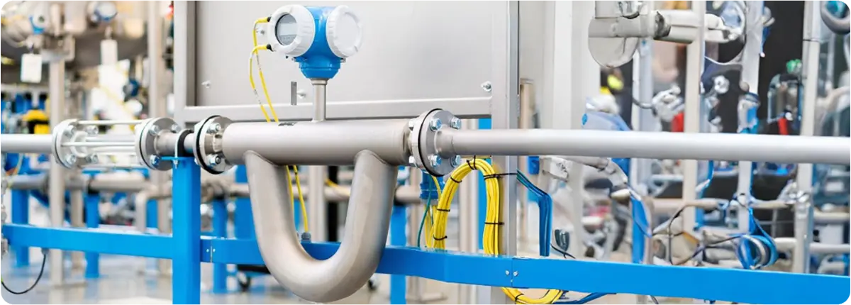
Coriolis flowmeters measure mass flow by detecting the phase shift caused when fluid passes through vibrating tubes. The tubes are set into oscillation by electromagnetic drivers. As the fluid flows, a measurable phase difference appears between the inlet and outlet ends of the tube, which is proportional to the mass flow.
Basic equation:
ṁ = k · Δφ
ṁ: mass flow rate (kg/s), k: calibration constant, Δφ: phase shift (radians).
Additionally, the natural vibration frequency of the tubes is used to measure fluid density:
ρ = f(ω)
ρ: density, ω: vibration frequency.
STRUCTURAL FEATURES
- Measuring tubes: U-shaped or dual straight tube designs
- Materials: Stainless steel, Hastelloy, or corrosion-resistant alloys
- Sensors: Electromagnetic or optical detection
- Output: 4-20 mA, HART, Profibus, Modbus, Foundation Fieldbus
- Additional functions: Density, temperature, and viscosity measurement
ADVANTAGES AND LIMITATIONS
Advantages:
- Direct mass flow measurement
- Very high accuracy (±0.1% – ±0.2%)
- Simultaneous density and temperature measurement
- No moving parts, minimal maintenance
Limitations:
- High initial cost
- Heavy and expensive for large pipe diameters
- Sensitive to vibrations and installation conditions
APPLICATION AREAS
- Chemical and petrochemical industry: measurement of acids, bases, and solutions
- Oil and gas industry: mass flow measurement
- Food and beverage production: sugar solutions, milk, beer, etc.
- Pharmaceutical industry: precise formulations
- Energy sector: fuel feed and process control
STANDARDS AND CALIBRATION
- ISO 10790: International standard for Coriolis flowmeters
- OIML R 137: International standard for gas flow measurement devices
- ATEX-certified versions: For explosive environments
- Regular calibration is essential to maintain accuracy
CONCLUSION
Coriolis flowmeters provide unmatched accuracy and versatility by offering direct mass flow measurement combined with density and temperature monitoring. They are indispensable instruments in modern process industries, particularly where precision and reliability are critical.