Posts

Valves are key parts in systems that manage the flow of fluids. They’re used in many industries, and keeping them in good shape is crucial for smooth and cost-effective operations. This guide offers simple tips to help you make your valves last longer.

REGULAR CHECK-UPS AND CARE :

  1. Look Them Over: Check your valves often for signs like rust, leaks, or wear and tear. Fix issues quickly to stop them from getting worse.
  2. Keep Them Lubed: Use the right kind of grease or oil on valve parts to cut down on wear. Follow the maker’s guidelines on when and what to use.
  3. New Seals: Valves have seals that can wear out. Replace them when they show signs of wear to keep a tight seal.

SMART USE :

  1. Don’t Push Limits: Keep valves within their stated pressure and heat limits to stop early wear.
  2. Easy Does It: Quick opening and closing can cause stress and damage. Be gentle to avoid extra wear.
  3. Cut the Shake: Too much shaking can cause valves to break early. Make sure they’re held firmly in place.

MATCH FLUIDS AND VALVE MATERIALS :

  1. Right Material: Pick valves made from materials that won’t corrode or break down when in contact with the fluids you’re using.
  2. Clean Fluids: Make sure fluids flowing through the valves are clean and don’t have stuff in them that could hurt the valve.

PROTECT FROM TOUGH CONDITIONS :

  1. Fight Rust: Use special coatings that fight rust for valves used in places that cause rust.
  2. Weather-Proof: For outdoor valves, make sure they’re shielded from harsh weather.

TEST AND ADJUST REGULARLY :

  1. Function Checks: Test your valves from time to time to make sure they’re working right. Fix any issues as soon as possible.
  2. Fine-Tune: Keep control valves well-tuned for accurate control of fluid flow.

PLAN AHEAD FOR REPLACEMENT :

  1. Be Proactive: Use monitoring tools to predict when valves might fail. Change them out before they cause problems.

TRAIN YOUR TEAM AND KEEP RECORDS :

  1. Teach Staff: Make sure your team knows how to handle valves correctly and how to spot problems.
  2. Keep Notes: Log all valve work to help plan for future care and problem-solving.

GET EXPERT ADVICE :

  1. Talk to Makers: For the best care tips, consult the people who made the valve.

CONCLUSION :

Taking good care of your valves can mean less downtime, fewer costs, and fewer surprises. A mix of regular care, smart use, and good record-keeping can go a long way in making your valves last longer.
 

When it comes to fluid control systems, choosing the right valve can significantly impact performance and efficiency. Butterfly valves and gate valves are commonly used and each has its own set of features and advantages. Below, we’ve compared them side by side.

Butterfly Valve Gate Valve
Construction and Design Features a quarter-turn valve with a disc-shaped closure element that rotates around an axis perpendicular to the flow direction. Utilizes a sliding gate-like disk that moves up and down to control the flow. The disk completely blocks the flow when fully closed.
Working Principle Operates with a quick quarter-turn motion, suitable for rapid opening and closing but not for precise flow control. Operates by lifting or lowering the gate disk, providing a linear on/off control.
Advantages Quick operation, compact design, lower cost, lower pressure drop. Excellent sealing capabilities, minimal pressure drop when fully open, can handle high temperatures and pressures.
Disadvantages Limited throttling capability, potential for cavitation and erosion, potential for leakage due to wearing sealing surfaces. Slower operation, bulkier design, higher costs, and prone to potential stem leakage.
Weight (Approximate) Lighter due to compact design. Heavier due to the robust gate and stem construction.
Size Range Available in a wide range of sizes. Also available in various sizes but might be bulkier in larger sizes.
Price Range Generally cheaper, making them a cost-effective option. Typically more expensive, especially for larger sizes.

By understanding the comparative aspects of butterfly and gate valves, engineers and operators can make an informed decision based on specific needs such as flow control, temperature, pressure, and budget.

CONCLUSION :

Both types of valves have their own sets of advantages and disadvantages. Butterfly valves are generally lighter, quicker, and more cost-effective, making them suitable for certain applications. Gate valves, on the other hand, offer tight sealing and can handle high temperatures and pressures but come with a higher cost and slower operation. Therefore, choosing between the two depends on the specific requirements of your application.


Pneumatic valves are key parts in many systems for controlling liquids and gases. They use compressed air to work quickly and reliably. This guide explains how these valves work and where they are used.

HOW PNEUMATIC VALVES WORK :

Pneumatic valves use principles of fluid flow and air pressure. They have several important parts:

  1. Valve Body: This is the shell that holds all the other parts. It lets fluid or gas flow through it.
  2. Actuator: This part uses compressed air to open and close the valve. It turns air pressure into movement.
  3. Valve Seat: This creates a seal for the moving part of the valve. It helps to stop or allow flow.
  4. Closure Element: This is the moving part connected to the actuator. It opens or closes to control flow.
  5. Control Mechanism: These are the different ways to control the valve, like with electrical signals, air pressure, or levers.

HOW PNEUMATIC VALVES OPERATE :

  1. Closed Position: The valve is closed when the moving part sits against the valve seat, stopping flow.
  2. Opening the Valve: When air pressure is sent to the actuator, it moves the closure element. This opens the valve for flow.
  3. Controlling Flow: You can adjust how much the valve is open to control the flow rate.
  4. Closing the Valve: Removing or reversing the air signal makes the actuator move back, closing the valve.

WHERE PNEUMATIC VALVES ARE USED :

Pneumatic valves are used in many areas, like:

  • Factories and automated systems
  • Heating and cooling systems
  • Controlling industrial processes
  • Managing water and waste
  • Packaging products
  • Car manufacturing
  • Air-powered tools and machines

CONCLUSION :

Pneumatic valves are great for controlling fluid and gas. They’re quick, reliable, and used in many different industries. Knowing how they work can help you choose the right one for your needs.


In fluid control systems, being accurate and reliable is key. This is why valve limit switchboxes are important. They help make sure valves work well, which in turn improves the safety and efficiency of industrial processes. This guide will explain why using valve limit switchboxes with pneumatic actuators is a good idea.

WHAT ARE VALVE LIMIT SWITCHBOXES :

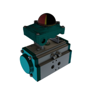
A valve limit switchbox is a small device that connects to a pneumatic actuator. Its main job is to tell the control system where the valve is. This information helps control the flow rate and ensures the valve is in the right position.

WHY USE VALVE LIMIT SWITCHBOXES :

  1. Checking Position: These switchboxes give real-time data on where the valve is—whether it’s fully open, fully closed, or somewhere in between. This helps to prevent mistakes and equipment damage.
  2. Safety: In high-stakes situations, like handling dangerous materials, knowing the exact position of the valve is crucial. The switchboxes make sure the valves are set up right, reducing the chance of leaks or accidents.
  3. Remote Checks: The data from these switchboxes can be sent to a control room far away. This allows workers to check the status of valves without having to go to each one, making things more efficient and safe.
  4. Finding Issues: Any irregularities in how the valve is working, like sticking or jamming, can be quickly spotted by looking at the switchbox data. Catching these problems early helps avoid downtime and expensive repairs.
  5. Better Processes: Knowing the exact position of valves helps fine-tune operations, which can save energy, improve product quality, and cut down on waste.

WHERE ARE VALVE LIMIT SWITCHBOXES USED :

You’ll find these switchboxes in different sectors like:

  • Oil and Gas : They help avoid leaks and keep things running smoothly in pipelines and refineries.
  • Water Treatment : They control water and chemical flows in purification plants.
  • Chemical Processing : These switchboxes help prevent spills or contaminations by keeping valves in check.
  • Power Generation : In power plants, they help control the flow of steam, gases, and other fluids.
  • Manufacturing : Here, they help ensure product quality by keeping valves in the right positions.

CONCLUSION :

Valve limit switchboxes are vital for making sure fluid control systems work well. They provide the real-time data needed for safe, efficient operations. Using them with pneumatic actuators can result in better productivity and cost savings.

Valve limit switchboxes are key parts in factories, helping control and monitor valve positions. This guide explains how these boxes are classified and how they work.

UNDERSTANDING VALVE SWITCHBOXES :

A valve limit switchbox keeps track of a valve’s position. It sends this data to a control system or person. These boxes come in many styles to fit different needs.

CLASSIFICATION OF VALVE LIMIT SWITCHBOXES :

  1. Mechanical Limit Switchboxes:
    • These use physical contact to sense the valve’s position.
    • A lever connected to the valve turns on a switch, sending data to the control system.
  2. Inductive Limit Switchboxes:
    • These use sensors close to the valve to detect its position.
    • A magnetic field reacts with a metal target on the valve, sending a signal when they’re close.
  3. Magnetic Limit Switchboxes:
    • These use magnets and sensors to find out where the valve is.
    • The magnet’s field changes as the valve moves, helping the sensor figure out the position.

WORKING PRINCIPLE OF VALVE LIMIT SWITCHBOXES :

All these switchboxes share a common way of working:

  1. Position Sensing:
    • The box always checks the valve’s position.
    • When the valve moves, it triggers a mechanism in the switchbox.
  2. Signal Transmission:
    • The box sends an electrical signal when the valve reaches a set point.
    • This signal goes to a control system to show the valve’s status.
  3. Feedback and Control:
    • The control system uses this data to make choices.
    • For instance, it can stop the valve when it’s fully open or closed.

ADVANTAGES OF VALVE LIMIT SWITCHBOXES :

These switchboxes bring several good points to system control:

  • Accuracy: They give precise and reliable info about valve positions, avoiding mistakes.
  • Remote Monitoring: People can check valve positions from afar, saving time and effort.
  • Emergency Shutdown: In emergencies, these boxes help make quick, safe choices.

CONCLUSION :

Valve limit switchboxes are vital for keeping industrial processes safe and efficient. Knowing how they’re classified and how they work helps people choose the right one for their needs. These switchboxes improve valve performance, boost safety, and make operations more smooth.