Posts

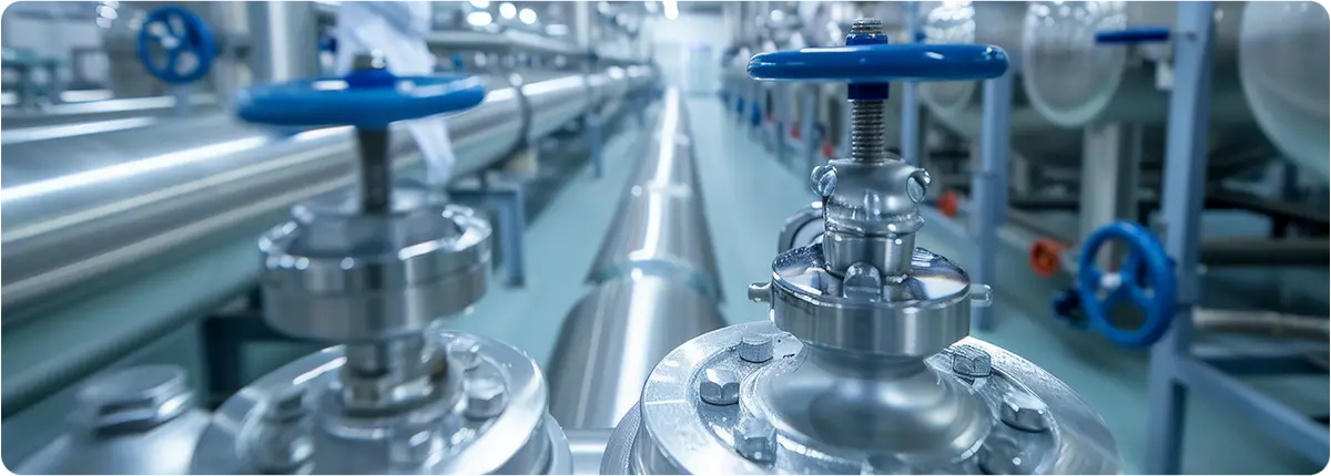
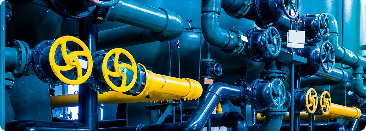
Natural gas plays a vital role in meeting the world’s energy demand, and its safe transmission depends heavily on the performance of valves installed in pipelines. Valves regulate flow, control pressure, isolate sections of the pipeline, and provide emergency shutdown capabilities. Choosing the wrong type of valve not only reduces efficiency but can also lead to severe safety risks.

This article examines the types of valves used in natural gas pipelines, their features, material and standard requirements, and key factors engineers must consider when selecting them.

Natural Gas Pipelines

MAIN VALVE TYPES IN NATURAL GAS PIPELINES

Ball Valves

  • The most widely used valves in natural gas systems.
  • Advantages: Full-bore design minimizes pressure drop. Operated with a quarter-turn (90°), making them ideal for emergency shutoff.
  • Applications: Commonly used in long-distance transmission pipelines and city gate stations.

Gate Valves

  • Preferred in large-diameter transmission lines.
  • Advantages: Minimal flow resistance when fully open.
  • Disadvantages: Slower to operate compared to ball valves.
  • Example: Frequently installed in 36” and larger pipeline sections.

Butterfly Valves

  • Compact and cost-effective solutions for large-diameter lines.
  • Advantages: Lightweight, simple construction, and economical.
  • Applications: More common in distribution networks operating at medium pressure.

Control Valves

  • Designed to regulate flow rate and pressure.
  • Features: Can be integrated into SCADA and automation systems.
  • Example: LNG terminals rely on control valves for continuous adjustment of gas flow.

Safety and Relief Valves

  • Protect pipelines from overpressure events.
  • Operation: Open at a preset pressure, venting gas to the atmosphere.
  • Standard: Designed according to API 520/521.

Check Valves

  • Prevent reverse flow, protecting compressors and downstream equipment.
  • Example: A standard component in compressor stations.

MATERIAL SELECTION AND STANDARDS

  • Common Materials:
    • Carbon steel (ASTM A105, A216 WCB)
    • Low-temperature steels (ASTM A350 LF2)
    • Stainless steels (AISI 304, 316) for corrosive environments
  • Relevant Standards:
    • API 6D – Pipeline valves
    • ASME B16.34 – Pressure-temperature ratings
    • ISO 14313 – International pipeline valve standard

KEY SELECTION CRITERIA

Pressure Class

Valves are designed according to ANSI classes ranging from 150 to 2500.
Example: A 70-bar transmission pipeline typically requires a Class 600 valve.

Flow Coefficient (Cv)

The capacity of a valve is defined by its flow coefficient:

Q = Cv · √(ΔP / G)

  • Q: Flow rate (m³/h)
  • ΔP: Pressure drop (bar)
  • G: Specific gravity of gas

Temperature and Operating Conditions

  • Natural gas is usually transported between -20 °C and +60 °C.
  • Valve seals and body materials must be compatible with this range.

Automation and Remote Control

  • Critical stations require actuated valves (electric, pneumatic, or hydraulic).
  • Example: City gate stations often use pneumatically actuated ball valves integrated into SCADA.

Safety and Maintainability

  • Valves with Double Block & Bleed (DBB) design improve maintenance safety.
  • They also allow testing of pipeline segments under pressure.

REAL-WORLD APPLICATIONS

  • TANAP Project (Turkey): The 1,850 km Trans-Anatolian Natural Gas Pipeline relies on API 6D ball valves for high-pressure transmission.
  • European Distribution Networks: Medium-pressure networks frequently use butterfly and control valves.
  • Compressor Stations: Check valves are indispensable to prevent backflow damage.

CONCLUSION

Valves in natural gas pipelines are essential for safety, efficiency, and operational continuity. From ball and gate valves to butterfly, control, and relief valves, the selection depends on pipe diameter, pressure class, flow capacity, and automation requirements.

Improper valve selection can result in high operational costs or serious safety hazards. Therefore, engineers must rely on API, ASME, and ISO standards, ensuring each valve is designed and chosen for the specific conditions of the pipeline.

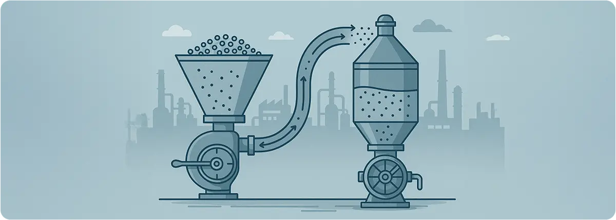
Pneumatic conveying systems are widely used in modern industries to transport powders, granules, and bulk solids through pipelines using air as the carrier medium. They offer a closed, hygienic, and efficient method of material handling, making them indispensable in sectors such as food, cement, chemicals, and pharmaceuticals.

This article explores the principles of pneumatic conveying, key engineering calculations, and the types of valves that ensure efficiency and reliability within these systems.

Pneumatic Conveying Systems

PRINCIPLES OF PNEUMATIC CONVEYING

The core concept of pneumatic conveying is to create a pressure differential that moves solid particles suspended in an air stream through a pipeline. There are two major approaches:

  • Positive Pressure Systems: A blower or compressor pushes air into the line, carrying the material forward.
  • Vacuum Systems: A vacuum pump creates negative pressure, pulling material into the line.

Conveying can also be classified based on the phase density:

  • Dilute Phase Conveying: Material is suspended in high-velocity air (typically 15–30 m/s).
  • Dense Phase Conveying: Material moves as plugs or layers at lower velocities (4–12 m/s), reducing degradation and wear.

ENGINEERING CALCULATIONS

Mass Flow Rate of Material:
ṁ = ρs · A · vs

Where:
• ṁ: Mass flow rate (kg/s)
• ρs: Bulk density of material (kg/m³)
• A: Pipe cross-sectional area (m²)
• vs: Conveying velocity of solids (m/s)

Air Volume Flow:
Q = W / (ρa · va)

Where:
• W: Mass of material to be conveyed (kg/s)
• ρa: Air density (kg/m³)
• va: Air velocity (m/s)

Pressure Drop in Pipelines:
ΔP = f · (L / D) · (ρa v² / 2)

Where:
• f: Friction factor
• L: Pipe length (m)
• D: Pipe diameter (m)
• ρa: Air density (kg/m³)
• v: Air velocity (m/s)

Engineering Note: The minimum conveying velocity must remain above the saltation velocity (critical settling velocity), typically around 15–20 m/s, to avoid particle deposition.

VALVES IN PNEUMATIC CONVEYING SYSTEMS

Valves are critical for ensuring air tightness, material dosing, and flow control. The most common valve types include:

  • Butterfly Valves: Provide wide openings and minimal pressure drop, ideal for frequent on/off operations.
  • Slide Gate Valves: Used to shut off or divert material flow; common in cement and grain systems.
  • Rotary Airlock Valves: Serve as both feeders and valves, ensuring controlled material entry while maintaining system air pressure.
  • Check Valves: Prevent reverse flow, protecting equipment from pressure surges.
  • Quick-Acting Valves: Enable fast line switching in highly automated plants.

ENERGY EFFICIENCY AND AUTOMATION

  • Actuated Valves: Pneumatic or electric actuators ensure precise control in automated systems.
  • SCADA/PLC Integration: Centralized monitoring and control optimize the entire conveying network.
  • Energy Efficiency: Proper valve selection and sealing can reduce air leakage, cutting energy consumption by up to 15%.

APPLICATIONS

  • Food Industry: Flour, sugar, coffee, milk powder.
  • Chemical and Pharmaceutical: Fine chemicals, active ingredients, powdered excipients.
  • Construction Materials: Cement, lime, gypsum.

CONCLUSION

The efficiency of pneumatic conveying systems depends not only on pipeline design and air supply but also on the valves that regulate flow and maintain system integrity. From butterfly and slide gates to rotary airlocks and check valves, the correct valve choice ensures reliable operation, reduced energy costs, and improved system longevity. With automation and modern valve technology, pneumatic conveying continues to be a robust, flexible, and cost-effective solution for bulk material handling.

In industrial processes, choosing the right valve is not just about cost—it is about safety, reliability, energy efficiency, and long-term performance. In many applications, multiple valve types may work, but the best choice depends on technical priorities such as line size, pressure and temperature ratings, cycle life, footprint, and operating speed.

This article expands on these five factors and provides a practical, engineering-based framework to guide valve selection.

Right Product

LINE SIZE: WHEN DIAMETER ≥ 2”

For line sizes of 2 inches (DN 50) and larger, butterfly and gate valves often become the most economical solutions.

  • Butterfly valves are lightweight, cost-effective, and easy to automate with actuators.
  • Gate valves are preferred for slurry or particulate media and where linear throttling is needed.

Engineering Note – Pressure Drop:
The Darcy–Weisbach equation highlights the impact of diameter on frictional losses:
ΔP = f · (L/D) · (ρv²/2)

PRESSURE–TEMPERATURE RATINGS

For high-pressure and high-temperature service, ball valves and angle seat valves provide the most reliable shutoff and sealing characteristics.

  • Ball valves: robust body, metal seats, suitable for hydrocarbon and chemical service.
  • Angle seat valves: excellent thermal and pressure tolerance, but limitations at very large sizes.

Stress Consideration (Thin-Walled Cylinder):
σθ ≈ (P · D) / (2t)

CYCLE LIFE: HIGH-SPEED, HIGH-FREQUENCY APPLICATIONS

Applications such as filling, dosing, or bottling lines may require thousands of valve cycles per day.

  • Angle seat valves (pneumatic actuation) and solenoid valves (electric actuation) deliver long cycle lives and very fast response times.
  • Ball and butterfly valves are sufficient for low-cycle applications such as process isolation.

Engineering Note – Water Hammer:
Fast-closing valves increase water hammer risks. Actuator ramp times should be tuned, or non-slam designs selected, to reduce surge pressures.

FOOTPRINT AND SPACE CONSTRAINTS

In compact skid-mounted systems, modular units, or OEM equipment, angle seat and solenoid valves are preferred due to their small footprint and integrated actuation.

  • Reduced weight lowers structural stress.
  • Smaller size simplifies maintenance and installation.

OPERATING SPEED

  • Angle seat valves provide the fastest open/close times, improving precision in dosing applications.
  • Solenoid valves also offer high switching speed but are limited by Cv (flow coefficient).
  • Larger valves (butterfly, gate) have slower actuation speeds but are acceptable in isolation duties.

HYDRAULIC SIZING: CV, VALVE AUTHORITY, AND CONTROL STABILITY

Flow Coefficient Equation (US units):
Q = Cv · √(ΔP / Gf)

Where:
Q: flow rate
Cv: valve flow coefficient
ΔP: pressure drop
Gf: specific gravity

Valve Authority:
N = ΔPvalve / ΔPtotal
For control valves, an authority between 0.3 and 0.7 is usually recommended for stability.

MATERIAL AND MEDIA COMPATIBILITY

  • Stainless steel, bronze, and high-performance polymers should be matched to the fluid’s chemical and temperature properties.
  • For abrasive or slurry service, gate valves and hardened seat designs are preferred.
  • For clean steam or hygienic service, angle seat or sanitary ball valves are most suitable.

AUTOMATION AND ACTUATION

  • Pneumatic actuators: fast, safe, explosion-proof.
  • Electric actuators: easy integration, low maintenance.
  • Hydraulic actuators: high torque, suitable for large valves.

Butterfly and gate valves in large diameters are usually the most economical to automate.

QUICK COMPARISON MATRIX

Factor / Valve Type Ball Butterfly Gate Angle Seat Solenoid
≥ 2” line size Moderate High High Low Low
High P/T rating High Medium Medium High Low
Cycle life Medium Medium Low Very High High
Compact footprint Medium Medium Low High High
Operating speed Medium Medium–High Low Very High High
Slurry media Low–Medium Medium High Medium Low
Automation cost Medium High Medium High High

STEP-BY-STEP VALVE SELECTION GUIDE

  1. Define line size, pressure, temperature, and flow range.
  2. Assess media characteristics: clean, corrosive, or particulate.
  3. Define function: on/off, throttling, or directional control.
  4. Determine cycle frequency and response time requirements.
  5. Check space limitations and installation constraints.
  6. Select actuation method (manual, pneumatic, electric, hydraulic).
  7. Compare total cost of ownership (TCO), not just purchase price.

CONCLUSION

There is rarely a single “correct” valve for every case. Instead, multiple valve types may be suitable, and the best choice comes down to balancing line size, pressure-temperature requirements, cycle life, footprint, and actuation speed.

  • Butterfly/Gate → cost-effective for ≥ 2” pipelines
  • Ball/Angle Seat → reliable under high P/T
  • Angle Seat/Solenoid → best for fast, high-cycle operations
  • Compact valves → ideal for skid-mounted systems

By combining hydraulic calculations, material compatibility, automation needs, and lifecycle cost, engineers can make data-driven decisions that ensure safe, reliable, and efficient valve operation.