Posts

In industrial fluid handling systems, valve selection plays a crucial role in ensuring process efficiency, safety, and reliability. Among the wide variety of valve designs, plug valves stand out for their simple quarter-turn mechanism, compact design, and ability to provide tight shut-off. Their versatility makes them a popular choice across industries such as oil and gas, chemical processing, wastewater treatment, and power generation.
Plug Valves

DESIGN AND WORKING PRINCIPLE

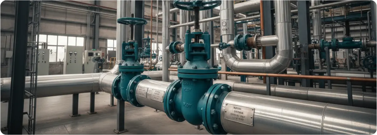
A plug valve consists of a cylindrical or tapered plug housed inside a valve body. The plug contains a through-hole (port) that allows fluid to pass through when aligned with the flow path. By rotating the plug 90 degrees, the flow is either fully opened or completely shut off.

Key design elements include:

  • Valve body: Typically made of cast steel, stainless steel, or ductile iron.
  • Plug: Cylindrical or conical, with one or more ports.
  • Sealing mechanism: Can be lubricated (using sealant) or non-lubricated (using sleeve or elastomer liners).
  • Actuation: Operated manually (lever or gear), pneumatically, hydraulically, or electrically.

TYPES OF PLUG VALVES

  • Lubricated Plug Valves: Use sealant injected around the plug to reduce friction and improve sealing. Common in oil & gas pipelines.
  • Non-Lubricated Plug Valves: Use PTFE or elastomer sleeves for low-maintenance operation. Popular in chemical and food processing.
  • Eccentric Plug Valves: Feature an off-centered plug for better sealing and lower torque. Used widely in wastewater systems.
  • Expanding Plug Valves: Mechanically expand during operation for bubble-tight sealing. Ideal for critical isolation services.
  • Multi-Port Plug Valves: Enable multiple flow paths for redirection between pipelines. Common in chemical and batch process applications.

APPLICATIONS OF PLUG VALVES

  • Oil & Gas: Upstream and downstream pipeline control.
  • Chemical Processing: Resistant to corrosion; often made from stainless steel or lined bodies.
  • Water/Wastewater: Eccentric plug valves used in treatment and distribution systems.
  • Power Generation: Cooling water, condensate, and auxiliary systems.
  • Food & Beverage: Non-lubricated hygienic designs prevent product contamination.

ADVANTAGES OF PLUG VALVES

  • Quick operation with quarter-turn mechanism
  • Compact and simple construction
  • Handles slurry and viscous fluids effectively
  • Available in multi-port configurations
  • Reliable sealing in high-pressure service
  • Durable under extreme temperature conditions

LIMITATIONS

  • High torque required for large diameters
  • Not ideal for throttling applications
  • Lubricated designs need periodic maintenance
  • Higher pressure drop compared to ball valves

SELECTION CRITERIA

  • Media Type: Corrosive, slurry, or clean fluids.
  • Pressure/Temperature: High pressure favors lubricated or expanding types.
  • Actuation: Manual for small valves; pneumatic or electric for automation.
  • Maintenance: Non-lubricated = lower maintenance, lubricated = longer service life.
  • Flow Path: Multi-port types reduce the need for multiple valves.

ENGINEERING NOTES

Flow Coefficient (Cv) is generally lower than ball valves due to internal restrictions. The pressure drop (ΔP) can be estimated using:

ΔP = Q² / (Cv² × SG)

Where Q = flow rate (gpm), and SG = specific gravity. Torque varies based on valve size, sealing type, and medium; actuator sizing must account for torque demand.

COMPARISON TABLE

Feature Plug Valves Ball Valves Gate Valves
Operation Quarter-turn Quarter-turn Multi-turn
Sealing Good to bubble-tight Excellent shut-off Moderate
Throttling Limited Limited Fair
Maintenance Medium Low Medium
Applications Oil & gas, wastewater General process, utilities Pipeline isolation

CONCLUSION

Plug valves are reliable, versatile, and efficient solutions for quick shut-off and flow control applications. Their various configurations — including lubricated, non-lubricated, eccentric, expanding, and multi-port types — make them adaptable to diverse industrial needs. With proper selection and maintenance, plug valves provide long-term performance, minimize downtime, and optimize operational cost efficiency.
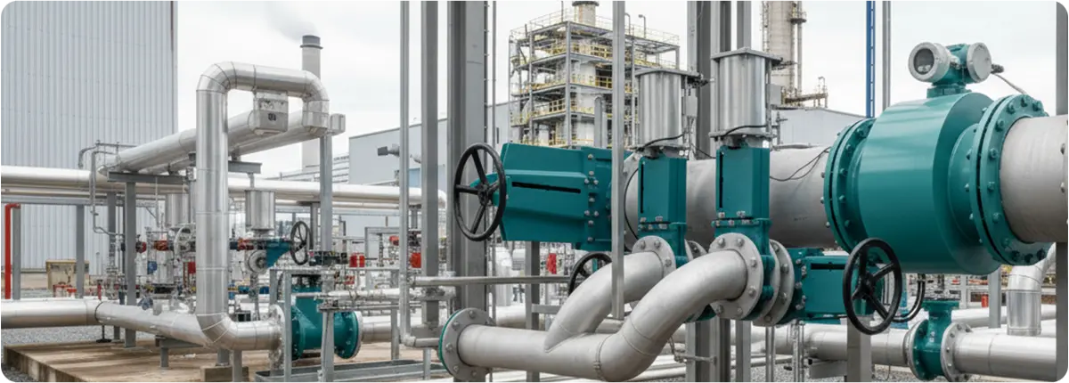
Knife gate valves are a specialized type of shut-off valve designed to handle fluids with suspended solids, slurries, or fibrous materials. Unlike standard gate valves, which use a wedge-shaped gate, knife gate valves use a thin, sharp-edged blade that can cut through thick media, making them indispensable in industries such as wastewater treatment, mining, pulp & paper, and chemical processing.

Knife Gate Valves

WORKING PRINCIPLE

The core principle of a knife gate valve is simple yet effective. When actuated, a flat blade (the ‘knife’) slides down into the valve seat, cutting through the media and forming a tight seal. In the open position, the blade retracts completely, allowing for a nearly unobstructed flow path.

  • Open position: Full-bore flow with minimal pressure drop.
  • Closed position: The knife-shaped disc cuts through solids, providing reliable shutoff.

DESIGN FEATURES

Knife gate valves are built for durability in harsh operating environments:

  • Body construction: Typically cast iron, ductile iron, carbon steel, or stainless steel.
  • Gate design: Sharp-edged stainless steel blade to shear through solids.
  • Seat options: Soft seats (elastomer, PTFE) for tight shutoff, or metal seats for high-temperature/abrasive applications.
  • Actuation: Manual (handwheel), pneumatic, hydraulic, or electric actuators.
  • Sizes & ratings: DN 50–DN 1200, usually up to PN 10 or ANSI Class 150.

APPLICATIONS

  • Wastewater treatment plants: Managing sludge and thick waste streams.
  • Mining industry: Controlling abrasive slurries of ore, sand, and tailings.
  • Pulp & paper mills: Handling fibrous pulp mixtures.
  • Chemical industry: Managing corrosive fluids with solid particles.
  • Food industry: Processing thick pastes, starches, or viscous ingredients.

ADVANTAGES

  • Cuts through solids and fibrous materials.
  • Compact design with minimal space requirements.
  • Low-pressure drop when fully open.
  • Cost-effective for large-diameter pipelines.
  • Easy to maintain with replaceable seats and seals.

LIMITATIONS

  • Not suitable for high-pressure applications above PN 10.
  • Slower operation compared to quarter-turn valves.
  • Not ideal for throttling; mainly on/off service.
  • Seat wear with abrasive slurries requires maintenance.

SELECTION CRITERIA

Factors to consider:

  1. Media characteristics: solids, abrasiveness, chemical composition.
  2. Pressure and temperature ratings.
  3. Actuation method: manual vs. automated.
  4. Sealing requirements: soft seats vs. metal seats.
  5. Installation space: vertical installation recommended.

COMPARISON WITH STANDARD GATE VALVES

  • Knife gate valve: Designed for slurry and solids, sharper disc, low-pressure ratings.
  • Standard gate valve: Designed for clean liquids and gases, higher pressure ratings, wedge-shaped gate.

ENGINEERING NOTES

The flow coefficient (Cv) of a knife gate valve is relatively high in the fully open position:

Q = Cv * sqrt(ΔP / SG)

  • Q = Flow rate (GPM)
  • Cv = Valve flow coefficient
  • ΔP = Pressure drop (psi)
  • SG = Specific gravity of fluid

Recommended slurry velocity: 1.5–3.5 m/s.

CONCLUSION

Knife gate valves play a vital role in industries dealing with challenging fluids. Their unique design enables them to handle slurries, viscous materials, and fibrous suspensions effectively. Proper selection ensures reliable operation, safety, and long service life.

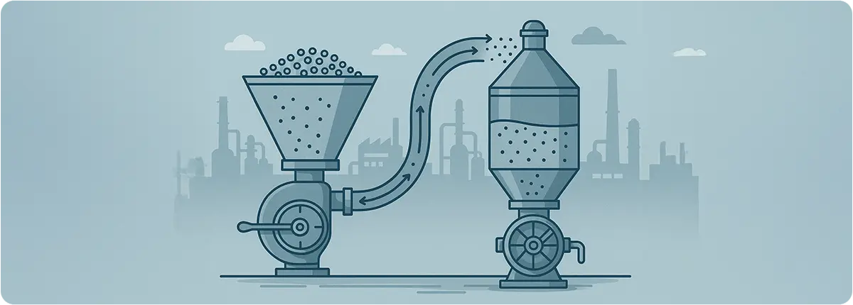
Pneumatic conveying systems are widely used in modern industries to transport powders, granules, and bulk solids through pipelines using air as the carrier medium. They offer a closed, hygienic, and efficient method of material handling, making them indispensable in sectors such as food, cement, chemicals, and pharmaceuticals.

This article explores the principles of pneumatic conveying, key engineering calculations, and the types of valves that ensure efficiency and reliability within these systems.

Pneumatic Conveying Systems

PRINCIPLES OF PNEUMATIC CONVEYING

The core concept of pneumatic conveying is to create a pressure differential that moves solid particles suspended in an air stream through a pipeline. There are two major approaches:

  • Positive Pressure Systems: A blower or compressor pushes air into the line, carrying the material forward.
  • Vacuum Systems: A vacuum pump creates negative pressure, pulling material into the line.

Conveying can also be classified based on the phase density:

  • Dilute Phase Conveying: Material is suspended in high-velocity air (typically 15–30 m/s).
  • Dense Phase Conveying: Material moves as plugs or layers at lower velocities (4–12 m/s), reducing degradation and wear.

ENGINEERING CALCULATIONS

Mass Flow Rate of Material:
ṁ = ρs · A · vs

Where:
• ṁ: Mass flow rate (kg/s)
• ρs: Bulk density of material (kg/m³)
• A: Pipe cross-sectional area (m²)
• vs: Conveying velocity of solids (m/s)

Air Volume Flow:
Q = W / (ρa · va)

Where:
• W: Mass of material to be conveyed (kg/s)
• ρa: Air density (kg/m³)
• va: Air velocity (m/s)

Pressure Drop in Pipelines:
ΔP = f · (L / D) · (ρa v² / 2)

Where:
• f: Friction factor
• L: Pipe length (m)
• D: Pipe diameter (m)
• ρa: Air density (kg/m³)
• v: Air velocity (m/s)

Engineering Note: The minimum conveying velocity must remain above the saltation velocity (critical settling velocity), typically around 15–20 m/s, to avoid particle deposition.

VALVES IN PNEUMATIC CONVEYING SYSTEMS

Valves are critical for ensuring air tightness, material dosing, and flow control. The most common valve types include:

  • Butterfly Valves: Provide wide openings and minimal pressure drop, ideal for frequent on/off operations.
  • Slide Gate Valves: Used to shut off or divert material flow; common in cement and grain systems.
  • Rotary Airlock Valves: Serve as both feeders and valves, ensuring controlled material entry while maintaining system air pressure.
  • Check Valves: Prevent reverse flow, protecting equipment from pressure surges.
  • Quick-Acting Valves: Enable fast line switching in highly automated plants.

ENERGY EFFICIENCY AND AUTOMATION

  • Actuated Valves: Pneumatic or electric actuators ensure precise control in automated systems.
  • SCADA/PLC Integration: Centralized monitoring and control optimize the entire conveying network.
  • Energy Efficiency: Proper valve selection and sealing can reduce air leakage, cutting energy consumption by up to 15%.

APPLICATIONS

  • Food Industry: Flour, sugar, coffee, milk powder.
  • Chemical and Pharmaceutical: Fine chemicals, active ingredients, powdered excipients.
  • Construction Materials: Cement, lime, gypsum.

CONCLUSION

The efficiency of pneumatic conveying systems depends not only on pipeline design and air supply but also on the valves that regulate flow and maintain system integrity. From butterfly and slide gates to rotary airlocks and check valves, the correct valve choice ensures reliable operation, reduced energy costs, and improved system longevity. With automation and modern valve technology, pneumatic conveying continues to be a robust, flexible, and cost-effective solution for bulk material handling.

Proactive maintenance practices can add years to the operational lifespan of ball valves.
Ball valves are essential components in fluid and gas control systems used across industries such as oil & gas, chemical processing, food and beverage manufacturing, machinery production, and automotive assembly and maintenance.

Compared to gate or globe valves, ball valves are often favored because they offer:

  • Compact, cost-efficient designs
  • Quick open/close operation
  • Reliable performance under high pressure, high volume, and high temperature
  • Strong resistance to corrosion and mechanical wear
  • Long service life
  • Compatibility with a wide range of industrial processes

Most ball valves are designed to require little to no maintenance and are eventually replaced once they reach the end of their service life. However, with the right preventive strategies, it is possible to extend their lifespan by several years, reducing both downtime and replacement costs.

maintenance

FACTORS INFLUENCING BALL VALVE LIFESPAN

While manufacturers typically estimate the service life of a ball valve at 8–10 years, real-world performance can be extended with proper care. The following factors have the greatest impact:

ACTUATION METHOD
Selecting the correct actuation type improves safety, reduces maintenance expenses, and ensures optimal uptime. Pneumatic actuated ball valves, for example, are highly durable in high-pressure systems as long as a compressed air supply is available.

DESIGN
Ball valves are available in one-piece, two-piece, and three-piece configurations. One- and two-piece designs cannot be repaired—when they fail, they must be replaced. Three-piece designs allow for the removal and replacement of seals and seats without removing the entire valve from the system.

TEMPERATURE AND PRESSURE RATINGS
The closer the operating conditions are to the valve’s maximum temperature and pressure limits, the more frequently maintenance or replacement will be required. High-cycle and high-pressure applications put significantly more stress on valve components.

MEDIA CHARACTERISTICS
Ball valves are designed for clean fluids and gases. Any abrasive particles present in the media can damage the valve’s internal surfaces, leading to leaks or actuator failure.

MATERIAL SELECTION
Common valve body materials include stainless steel, brass, bronze, and PVC. While PVC offers cost advantages and chemical resistance for certain applications, metal valves provide superior durability, higher temperature resistance, and broader media compatibility.

WHY BALL VALVE MAINTENANCE MATTERS

  • Extended Lifespan – Valves that last longer reduce replacement frequency, minimize downtime, and improve operational efficiency.
  • Safety – Regular inspections and proper installation reduce the risk of accidents, leaks, or catastrophic failures.
  • Uninterrupted Production – Many maintenance tasks can be performed without halting operations, keeping production lines active.
  • Cost Savings – Preventive maintenance lowers the need for emergency repairs and avoids unplanned capital expenditure.

HOW BALL VALVES WORK

A ball valve uses a spherical ball with a central bore to control flow.

  • When the bore aligns with the flow path, the valve is open.
  • Rotating the ball 90 degrees closes the valve by blocking the passage.

This quarter-turn operation allows quick shut-off and easy visual confirmation of valve position, but can also cause water hammer if closed too quickly.

PREVENTIVE MAINTENANCE FOR BALL VALVES

To get the best performance and lifespan from ball valves, maintenance should begin before any issues appear. Key steps include:

CORRECT INSTALLATION
Proper installation by trained professionals ensures optimal alignment, sealing, and performance.

REGULAR CLEANING
Annual cleaning (or more often in dusty or dirty environments) prevents buildup that could impair performance.

  • Use compressed air or gas-based cleaners for metal components.
  • Use alcohol- or water-based cleaners for non-metal parts.

LUBRICATION
Use synthetic, water-resistant, oil-based lubricants to reduce wear and maintain smooth operation. Avoid clay- or solid-based lubricants that can accumulate in the valve cavity.

SCHEDULED INSPECTIONS
Inspections should be carried out at least once a year—or more frequently for high-pressure and high-cycle applications. Checks should include:

  • Tightness of all hardware
  • Corrosion or mineral buildup
  • Leak detection
  • Full range of motion testing
  • Position indicator accuracy
  • Adequate exhaust and filtration conditions in the surrounding area

ANNUAL OVERHAUL
During planned shutdowns, remove valves from service, disassemble them, clean all parts, and replace worn components, especially seals and seats.

CONCLUSION

By selecting the right materials, using appropriate actuation methods, and following a disciplined preventive maintenance plan, ball valves can operate reliably for many years beyond their standard expected lifespan. This not only saves money but also protects plant safety and ensures uninterrupted production.