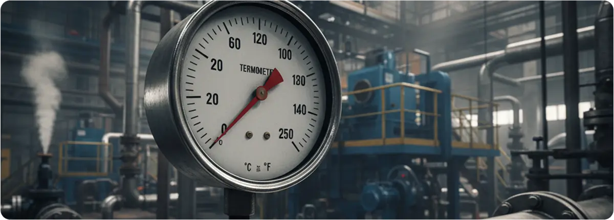
Thermometers are among the most fundamental measurement instruments, used for determining the temperature of gases, liquids, and solids. While the concept is simple—measuring heat energy and displaying it in understandable units—the technology behind thermometers has advanced significantly. From traditional glass devices to digital and infrared thermometers, their application spans industrial processes, laboratories, healthcare, food safety, and even everyday life.
WORKING PRINCIPLES
Thermometers operate by detecting physical changes in a material that correlate with temperature. Common principles include:
- Thermal Expansion: Liquids (such as mercury or alcohol) expand when heated and contract when cooled, moving along a calibrated scale.
- Electrical Resistance: Metals or semiconductors change resistance with temperature, a principle used in resistance thermometers (RTDs) and thermistors.
- Infrared Radiation: Infrared thermometers detect emitted thermal radiation, allowing non-contact temperature measurement.
- Pressure Changes: Gas or bimetallic thermometers utilize changes in pressure or the expansion of metals.
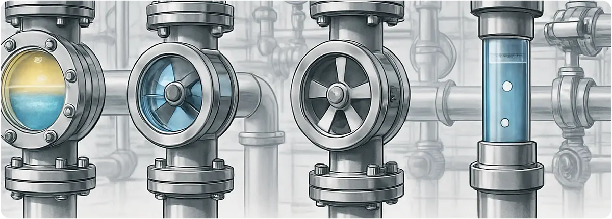
TYPES OF THERMOMETERS
- Liquid-in-Glass Thermometers: Traditional devices using mercury or alcohol in a sealed tube. Though accurate, mercury types are being phased out due to toxicity concerns.
- Bimetallic Thermometers: Utilize two metals with different expansion rates bonded together, bending with temperature change. Common in HVAC systems.
- Resistance Temperature Detectors (RTDs): Highly accurate and stable, typically made of platinum, widely used in industrial automation.
- Thermocouples: Generate a voltage when two dissimilar metals are joined and exposed to heat. Preferred for high-temperature industrial processes.
- Infrared Thermometers: Non-contact devices suitable for moving objects, dangerous surfaces, or sterile applications.
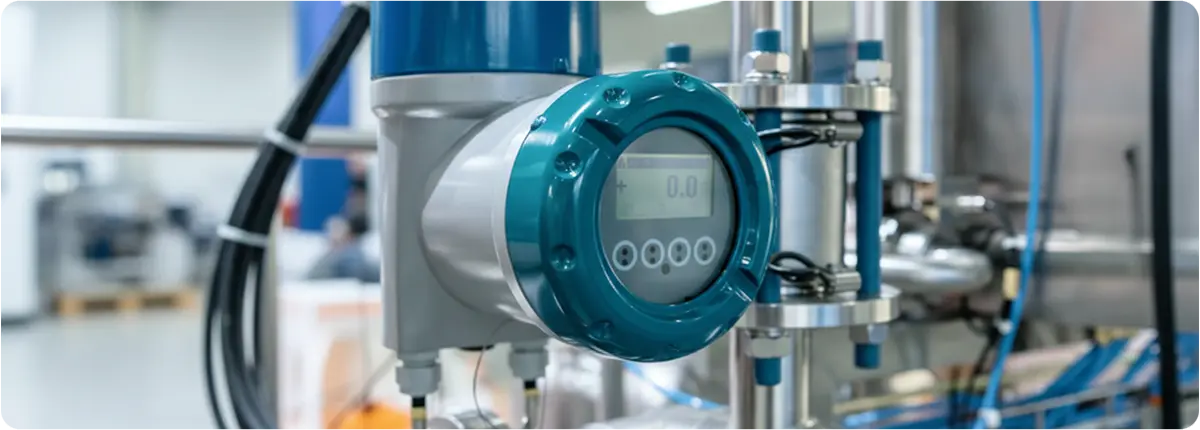
- Digital Thermometers: Provide easy-to-read electronic displays and are often integrated with data logging systems.
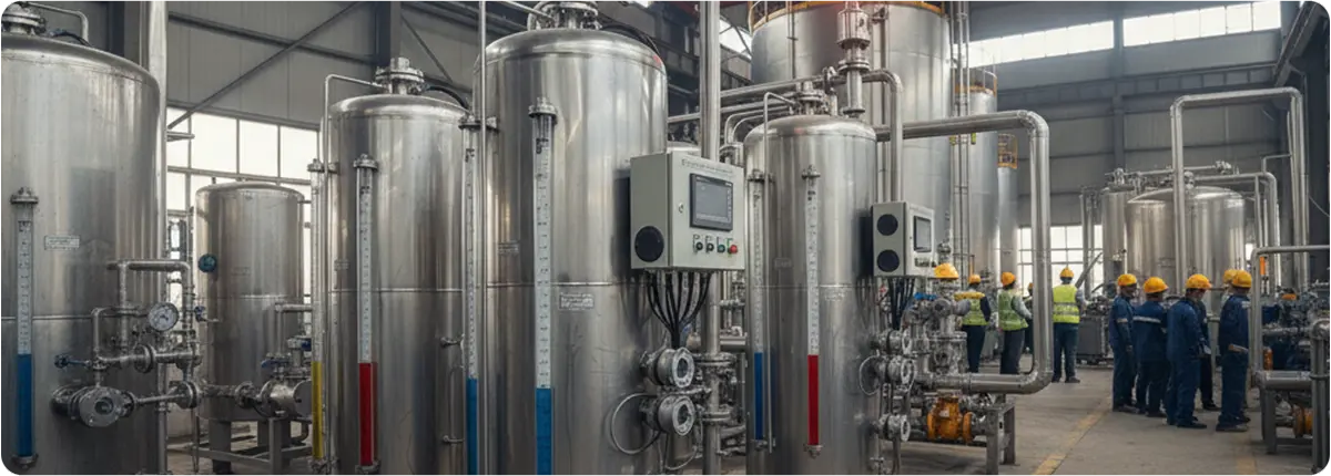
INDUSTRIAL APPLICATIONS
Thermometers play a crucial role in maintaining efficiency, safety, and product quality across industries:
- Chemical and Petrochemical Plants: Monitoring reaction temperatures, ensuring safety in pressurized vessels.
- Food and Beverage Industry: Ensuring compliance with hygiene and safety standards during processing and storage.
- Pharmaceutical Manufacturing: Precise monitoring of sensitive processes to maintain product efficacy.
- Power Plants: Measuring boiler, turbine, and exhaust gas temperatures to optimize energy production.
- HVAC Systems: Regulating building climate and energy consumption.
SELECTION CRITERIA
When selecting a thermometer for industrial or commercial use, the following should be considered:
- Measurement range and accuracy requirements
- Response time and stability
- Contact vs. non-contact measurement needs
- Environmental conditions (humidity, pressure, vibration)
- Integration with control and automation systems
ADVANTAGES OF MODERN THERMOMETERS
- High accuracy and repeatability
- Digital connectivity (IoT and smart factory compatibility)
- Safer alternatives to mercury-based devices
- Ability to measure extreme temperatures with minimal error
CONCLUSION
Thermometers, though seemingly simple, are indispensable tools for process control, safety, and quality assurance. From traditional mercury-based instruments to modern digital and infrared systems, the evolution of thermometers reflects advancements in technology and the growing demand for precision. In industrial contexts, proper thermometer selection ensures reliable operation, reduced downtime, and consistent product quality.