Posts

Managing the flow of liquids, gases, and steam in industries is essential. One tool that does this job exceptionally well is the single-acting pneumatic angle seat valve.

CONSTRUCTION AND DESIGN :

  • Materials: These valves are mainly made of stainless steel and other materials that don’t easily corrode.
  • Design: They come with a special angled seat. This ensures that when open, fluids flow smoothly.
  • Actuator: Found at the valve’s top, it uses compressed air. This part is the key to opening and closing the valve.

HOW THEY WORK :

  1. At Rest (Closed): The valve blocks fluid flow by default.
  2. Using Air (Open): Add compressed air to the actuator, and the valve opens, letting fluids flow.
  3. Stop Air (Closed): When the compressed air is gone, the valve closes again.

WHY THESE VALVES ARE EXCELLENT :

  1. Total Control: They give great control over fluid flows, helping keep processes stable.
  2. Quick Action: Thanks to the air power, they open and close swiftly.
  3. Energy Savers: They don’t use a lot of power, which means lower costs.
  4. Built to Last: Made sturdy, they don’t need changing or fixing often.

WHERE WE FIND THEM USEFUL :

  • Eating and Drinking: Controls flows when making or packaging food and drinks.
  • Making Medicine: Used in the processes that create drugs.
  • Clean Water: Found in places that treat water to make it clean.
  • Keeping Temperatures Right: In systems that heat or cool buildings.
  • Factory Machines: Common in systems that use machines to do tasks automatically.

CONCLUSION :

Single-acting pneumatic angle seat valves are vital tools in many industries. They’re loved for their ability to control flows precisely, react quickly, save energy, and last a long time. Using them means smoother processes, saving money, and less worry about repairs or replacements.

Manual angle seat valves serve as fundamental elements in fluid control systems. They ensure effective and accurate flow regulation for a myriad of industrial applications. Given their manual operation, they permit easy control over the flow of various media, such as liquids, gases, and steam. This piece delves into the construction, operational dynamics, perks, and application areas for manual angle seat valves.

CONSTRUCTIVE INSIGHTS :

  • Sturdy Make: Manual angle seat valves are durable, primarily fashioned from resilient materials like stainless steel or brass. Their special angled seat design facilitates an unhindered flow, leading to minimal pressure losses when the valve stands open.
  • User-Friendly Actuator: The manual actuator, positioned at the valve’s zenith, boasts a design that is simple to use and understand.

OPERATIONAL DYNAMICS :

  1. Default State (Closed): Initially, the valve’s closing component seals itself against the angled seat, halting fluid flow.
  2. Activation (Open Up): Fluid flow is enabled when the actuator is turned, lifting the closing component from the seat.
  3. Deactivation (Shut Down): Turning the actuator in the opposite direction makes the closing component reseat, terminating fluid flow.

WHY CHOOSE MANUAL ANGLE SEAT VALVES ?

  1. Effortless Usage: With a design geared towards simple handling, they fit perfectly where manual oversight is required.
  2. Budget-Friendly: Absent the need for extra pneumatic or electric parts, these manual valves emerge as cost-effective fluid control tools.
  3. Consistency: They guarantee stable and reliable flow control, solidifying process consistency.
  4. Zero Power Dependency: Their manual nature means they don’t hinge on external energy sources. This is a boon for areas with limited or no power access.

WHERE ARE THEY USED ?

From labs to large-scale industries, the reach of manual angle seat valves is broad:

  • Mini Industrial Setups: Best suited for manual flow governance in compact industrial zones or pilot facilities.
  • Research Labs: Laboratories prize them for their precision and simplicity in fluid control.
  • Water Treatment: They feature prominently in water treatment facilities for manually overseeing chemical dosing and flow metrics.
  • Textile Realm: They find a niche in controlling flow during dyeing or printing processes in the textile sector.
  • Diverse Industries: Their footprint is visible across many industries, standing out as reliable tools for manual fluid control.

CONCLUSION :

Offering versatility and efficiency in fluid control, manual angle seat valves are a favored pick across diverse scales and sectors. Their ease of use, affordability, and precision make them a coveted asset for manifold processes. Integrating these into fluid control frameworks empowers operators with refined control, ease, and consistency.

Solenoid valves are crucial in systems for fluid control. They come in two main types: pilot-operated and direct-acting. This guide dives into how they work, their differences, and where to use each.

WHAT ARE SOLENOID VALVES : 

A solenoid valve uses electric current to move a sealing element, like a plunger or diaphragm, and control fluid flow.

HOW DO SOLENOID VALVES WORK :

Here’s how these valves operate:

  • De-Energized State: When not powered, the valve is in its default position—either open or closed.
  • Energization: Applying current to the coil creates a magnetic field, moving the plunger or diaphragm.
  • Fluid Flow: The sealing element’s movement controls the fluid flow.
  • De-Energized Again: Removing the current brings the sealing element back to its default position.

TYPES OF SOLENOID VALVES :

Based on design, solenoid valves can be:

  • 2-Way: One inlet and one outlet; good for on/off control.
  • 3-Way: One inlet and two outlets; used for fluid direction change.
  • 4-Way: Two inlets and outlets; used for complex flow control.

PILOT-OPERATED VALVES :

These valves use a small pilot valve to control a main valve. When powered, the pilot valve opens, controlling the main valve via fluid pressure.

DIRECT-OPERATED VALVES :

Direct-acting valves work without a pilot valve. The coil’s magnetic field directly moves the sealing element.

DIFFERENCES BETWEEN PILOT-OPERATED AND DIRECT-ACTING :

  • Pressure: Pilot-operated can handle higher pressures.
  • Flow: Pilot-operated is better for high-flow applications.
  • Speed: Direct-acting valves respond quicker.
  • Power: Direct-acting usually uses less energy.

WHERE ARE SOLENOID VALVES USED :

These valves are used in:

  • Automotive: For controlling fuel and transmission fluid.
  • HVAC: To manage refrigerant and air flows.
  • Water Treatment: Essential for controlling water and chemicals.
  • Industrial Automation: For precise flow control.
  • Medical Equipment: To control gases and liquids in critical processes.

CONCLUSION :

Choosing between pilot-operated and direct-acting valves depends on your needs, like flow rates and pressure. These valves are key in many industries for efficient, precise fluid control.

Pneumatic actuators play an essential role in a multitude of industrial applications, converting compressed air into mechanical motion. These devices come in several designs, but one of the most fundamental distinctions is between single acting and double acting actuators. This guide delves deep into their operation, advantages, and best-fit scenarios.

PNEUMATIC ACTUATORS : THE FUNDAMENTALS

  • Functionality: Pneumatic actuators utilize compressed air to produce motion, which can be linear or rotational based on the design.
  • Control Mechanism: Actuators respond to pressure differentials in a control system, where compressed air is either introduced or vented from actuator chambers to generate motion.

SINGLE ACTING VS. DOUBLE ACTING ACTUATORS

  • Single Acting : These actuators use compressed air to move the actuator in one direction (either to open or close). A spring or external force is typically used to return the actuator to its original position. They are often referred to as “spring return” or “fail-safe” actuators because they return to a default position in case of air supply failure.

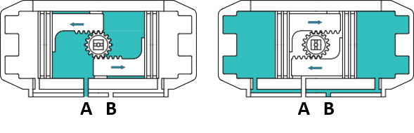
Air to port A forces the pistons outwards, causing the springs to compress, The pinion turns counterclockwise while air is being exhausted from port B.
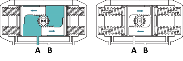
Loss of air pressure on port A, the stored energy in the springs forces the pistons inwards. The pinion turns clockwise while air is being exhausted from port A.

  • Double Acting: Double acting actuators use compressed air to move the actuator in both the opening and closing directions. They have two air ports to alternately apply pressure for open and close actions. Without air pressure, a double acting actuator will stay in its last position.

double acting Actuator

Air to Port A forces the pistons outwards, causing the pinion to turn counterclockwise while the air is being exhausted from Port B.

Air to Port B forces the pistons inwards, causing the pinion to turn clockwise while the air is being exhausted from Port A.

ADVANTAGES OF PNEUMATIC ACTUATORS :

  1. Energy Efficient: Only require air, making them optimal when air is available.
  2. Safe: Ideal for explosive environments due to the absence of sparks.
  3. Cost-Effective: Lower operational costs when compressed air is accessible.
  4. Rapid Response: Especially with single acting designs, the response time can be swift due to the spring mechanism.

WHERE THEY SHINE :

  • Single Acting: Best for safety-critical applications where default positions are vital during failures.
  • Double Acting: Essential for processes that require more precise control in both directions and where air supply is consistent.

TECHNICAL CONSIDERATIONS :

  • Force & Speed: Pneumatic actuators, especially double acting types, can provide fast actuation. Their force output is determined by the air pressure and actuator size.
  • Environmental Suitability: They excel in environments prioritizing cleanliness or safety, devoid of electricity or harmful fluids.

CONCLUSION :

In the realm of actuation, the choice of actuator has profound implications. Pneumatic actuators, specifically the distinction between single and double acting, cater to various applications based on their inherent advantages. A thorough understanding of their mechanics and functionalities enables industries to optimize performance and safety.

Electric actuators are key for managing fluid flows in various systems. They allow for remote valve operation, and come mainly in two types: on-off and modulating. Knowing the differences between these two types is vital for picking the best actuator for your needs. This guide will help you understand what sets them apart, what they’re good for, and where they best fit.

ON-OFF ELECTRIC ACTUATORS : THE BASICS

Functionality: On-off actuators work in a simple way: they either fully open or fully close a valve. Built-in limit switches help them detect when the valve is in the open or closed position for precise operation.

Control Mechanism: These actuators get a basic electrical signal. When told to open or close the valve, they keep going until they reach the instructed position. There’s no in-between; it’s either all open or all shut.

ADVANTAGES :

  1. Ease of Use: On-off actuators are simple to use, making them a good fit for basic valve control tasks.
  2. High Reliability: Their straightforward operation means less room for errors, adding to their reliability.
  3. Cost-Effective: Generally speaking, they’re cheaper than modulating actuators due to their simpler makeup.

WHERE THEY SHINE :

On-off actuators are great when you don’t need to adjust the valve to different positions. They’re used in isolation valves, safety shut-off valves, and scenarios requiring either full flow or total closure.

Modulating Electric Actuators: A Closer Look

Functionality: Unlike on-off actuators, modulating types can position a valve at any point between fully open and fully closed. This enables more precise control.

Control Mechanism: Modulating actuators get variable electrical inputs, letting them place the valve at multiple levels of openness. This allows for fine-tuning of flow rates.

ADVANTAGES :

  1. Pinpoint Control: These actuators offer nuanced control over valve positioning, making them ideal for specialized tasks.
  2. Flexibility: The capacity to place the valve at any point gives more control over process parameters.
  3. Process Optimization: When you need steady conditions for quality, efficiency, or safety, modulating actuators are the go-to choice.

WHERE THEY EXCEL :

Modulating actuators are ideal for tasks that require detailed valve positioning, like regulating flow rates in industrial settings, keeping specific pressure levels in pipelines, or jobs requiring gradual fluid flow changes.

CONCLUSION :

When it comes to fluid control, the type of actuator you choose plays a big role. On-off actuators offer binary, reliable control. Modulating actuators, on the other hand, give you more control and flexibility. Knowing the differences helps you choose the right actuator for your specific needs, leading to better performance, efficiency, and safety. By grasping these distinctions, you’ll be better equipped to make an informed choice that will serve your fluid control systems well.

Wafer butterfly valves are pivotal components in fluid control systems. Recognized for their compactness, lightweight nature, and straightforward installation, they serve a crucial role in regulating fluid flow across a variety of industries. Here’s a closer look at these valves, their design, and their applications.


DESIGN AND STRUCTURE :

    • Shape and Function: Named “wafer” because of their thin design, these valves consist of a central disc (the butterfly) mounted on a spindle. This disc rotates, controlling the flow of fluid through the valve.
    • Installation: Their body is sandwiched between two flanges in a pipeline, held in place by bolts, ensuring a secure and tight seal.

KEY FEATURES AND BENEFITS :

    • Space Efficiency: Their slim structure ensures they’re ideal for installations with limited space.
    • Light and Durable: Made typically from materials like ductile iron, these valves are both lightweight and robust.
    • Optimized Flow: Their design results in a minimal pressure drop when fully opened, ensuring efficient fluid movement.
    • Rapid Response: Operating on a quarter-turn principle, they can swiftly open or close, which is crucial for on/off control applications.
    • Cost Advantage: Simplicity in design coupled with durability translates to cost-effectiveness.

WHERE YOU’LL FIND THEM :

    • HVAC Systems: Their efficiency in regulating hot and cold water flow makes them staples in heating, ventilation, and air conditioning setups.
    • Water Management: Their cost-effectiveness and installation ease place them at the forefront in water supply, treatment plants, and irrigation systems.
    • Chemical Handling: Their ability to control flow efficiently makes them ideal for chemical processing plants, especially with corrosive fluids.
    • Food Production: Their design, which allows for easy cleaning, is crucial for the food and beverage industry, ensuring hygiene.
    • Fire Safety: Their rapid operation ensures they’re vital components in fire protection systems for quick and reliable shutoff control.

CONCLUSION :

Wafer butterfly valves are invaluable tools in fluid flow regulation, combining efficiency, cost-effectiveness, and reliability. For professionals in industries ranging from HVAC to food production, these valves remain integral for effective fluid handling and management.

Lug butterfly valves are strong, handy tools for controlling the flow of fluids. They have a special design with lugs (like small hooks) that lets them be easily put in or taken out of pipes without messing up the whole system. This article will explain how they’re built, why they’re good, and where they’re used.

HOW THEY’RE BUILT AND HOW THEY WORK :

These valves have a disc (think of it like a flap) that can spin inside the main body of the valve. The main body has these lugs on both sides. These lugs are there so the valve can be attached securely between two flanges (connecting points) in a pipe.

When you want fluids to flow, the disc spins to line up with the pipe, and fluids pass through easily. When you want to stop the flow, the disc turns to block the pipe.

WHY THEY’RE GOOD :

  • Two-way Sealing: These valves can be put in pipes in any direction and still work perfectly.
  • Quick to Install or Take Out: Because of the lugs, you can easily add or remove the valve without taking apart the whole pipe system.
  • Small and Light: These valves don’t take up much space and aren’t heavy. This is good for places where there isn’t much room and makes them cheaper to move around.
  • Saves Money: They’re simpler to make and put in, so they often cost less than other kinds of valves.

WHERE THEY’RE USED :

  • Chemical Plants: They’re used here because they seal really well and can be trusted to stop and start flow when needed.
  • Cleaning Water: These valves are used in places that treat water and manage wastewater since they’re easy to use and seal both ways.
  • Boats and Ships: They help control water and fuel flow in marine settings.
  • Making Electricity: Especially in places that need to control the flow of cooling water or air.
  • Putting Out Fires: They’re in fire systems because they can quickly stop or start the flow of water.

CONCLUSION :

Lug butterfly valves are a great choice for controlling fluid flow in many areas because they’re easy to use, efficient, and won’t break the bank. Whether you’re in the chemical business, water treatment, shipbuilding, power making, or even fire safety, these valves are key in managing fluids the right way.

Butterfly valves are an important type of valve widely used in various industrial applications today. However, many people are curious about how this popular valve type evolved over time and reached its modern form. In this article, we will examine the main stages of the historical development of butterfly valves. Starting from the mid-19th century, this development progressed from early simple designs to construction and performance improvements, culminating in today’s functionality through technological advancements.

EARLY PERIOD : The earliest examples of butterfly valves were used in water management and sewage systems from the mid-19th century. During this period, butterfly valves were simple, disk-shaped, and manually or gear-operated to control the flow.

ADVANCING YEARS : By the early 20th century, significant improvements were made in the design and functionality of butterfly valves. The materials and structures of the valves were enhanced, enabling more precise flow control.

INDUSTRIAL REVOLUTION AND PROGRESS : Progress in steel production, casting techniques, and processing methods led to more durable and efficient butterfly valves. The development of high-performance sealing materials improved the valves’ sealing properties and minimized the risk of leaks.

ADVANCED ACTUATION SYSTEMS : By the mid-20th century, more advanced actuation systems were employed. Electric motors, pneumatic, and hydraulic actuators began offering faster and more precise control.

INDUSTRIAL APPLICATIONS : Butterfly valves found their place in large facilities, water treatment plants, power plants, and more. Their popularity soared in large-diameter pipelines and industrial plants.

MODERN ERA : Advances in material technology, new coatings, and sealing techniques enhanced the valves’ lifespan and efficiency. The focus shifted towards reducing environmental impact.

FUTURE DEVELOPMENTS AND INNOVATIONS : The road ahead promises integration of smart sensors, automation technologies, and innovative designs to optimize butterfly valve performance.

In conclusion, the continuous technical and technological development of butterfly valves is a testament to their importance in ensuring efficiency and reliability in industrial processes.