Posts

Pilot-operated solenoid valves are widely regarded as the go-to solution for fluid control systems that require high flow rates and pinpoint accuracy. These valves operate through a dual-action mechanism involving both a pilot valve and a primary valve. This article aims to provide a comprehensive understanding of the construction, working principle, benefits, and various applications where pilot-operated solenoid valves excel.

IN-DEPTH CONSTRUCTION AND DESIGN :

Pilot Valve: Essentially a mini-valve within the larger structure, the pilot valve controls a smaller fluid flow, usually air or water.

Main Valve: This is the principal valve responsible for the bulk of the fluid flow and is controlled by the actions of the pilot valve.

Solenoid Coil: Integral to the operation, the coil generates the magnetic field that triggers the pilot valve.

DETAILED WORKING PRINCIPLE :

  1. De-energized State: Initially, both the pilot and main valves are closed.
  2. Energization and Pilot Valve Activation: Electrical current flows through the solenoid coil, opening the pilot valve.
  3. Main Valve Manipulation: The pilot valve’s opening leads to pressure build-up, which then opens the main valve.
  4. Fluid Flow: With the main valve open, large volumes of fluid can pass through.
  5. Cutting the Current: Removing electrical current closes the pilot valve, leading to the closing of the main valve, and thus stopping fluid flow.

COMPREHENSIVE ADVANTAGES :

  1. High Flow Capacity: Due to their design, these valves are excellent for high flow rate applications.
  2. Pressure Tolerance: Capable of handling higher pressures compared to their direct-acting counterparts.
  3. Stable Flow Control: The two-stage operation ensures stability and precision.
  4. Energy Efficiency: Consumes less power relative to its high-flow capabilities.

VARIED APPLICATIONS :

  1. Oil and Gas Sector: Utilized for controlling flow in pipelines and refineries.
  2. Water Treatment Plants: For chemical dosing and general water flow control.
  3. Industrial Automation: Used in various manufacturing processes for fluid control.
  4. Energy Sector: Plays a crucial role in steam and water flow control in power plants.

CONCLUSION :

When it comes to managing high flow rates with precision, pilot-operated solenoid valves are unparalleled. Their complex yet efficient two-stage mechanism allows for effective fluid control in a multitude of industrial applications. Thus, these valves are an excellent choice for engineers and system designers who require reliable, efficient, and precise fluid control solutions in demanding conditions.

Ball valves play a pivotal role in controlling fluid flow across numerous sectors. Thanks to their adaptability, trustworthiness, and user-friendliness, they’ve become the go-to for managing the movement of liquids and gases. This guide offers insights into the world of ball valves, spotlighting their types, functioning mechanics, material options, high-pressure usage, automated versions, essential approvals, and their typical industry applications.

COMMON BALL VALVE TYPES :

Ball valves come in a range of designs, each tailored for particular tasks and efficiency demands:

    • Floating Ball Valve: This type allows the ball to float slightly, with the fluid’s pressure facilitating a seal. Best for low to medium pressures. Commonly found in water supply, irrigation, and general industrial use.
    • Trunnion Ball Valve: This valve has a fixed ball held by trunnions. Perfect for high pressures, as it provides extra support, ensuring a tight seal. Typically used in oil, gas, petrochemicals, power generation, and heavy industries.
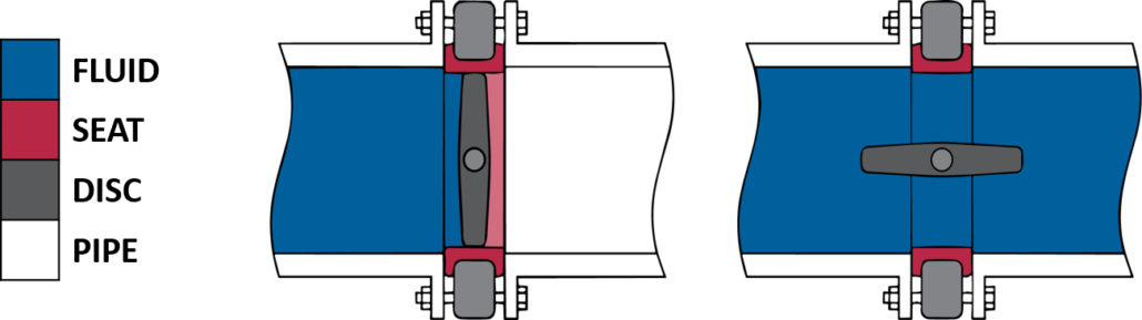
    • V-port Ball Valve: Features a V-shaped ball, allowing precise flow control. Ideal for the chemical sector, food processing, and HVAC systems requiring meticulous flow management.
    • Multi-Port Ball Valve: This valve has multiple ports, giving varied flow configurations. They’re frequently utilized in pharmaceuticals, chemical processing, and water treatment.
    • Cavity Filled Ball Valve: The ball’s cavity is filled, typically with PTFE, ensuring zero leakage. Primarily used where preventing leaks is paramount, like in chemical processing and petrochemical sectors.

HOW BALL VALVES WORK :

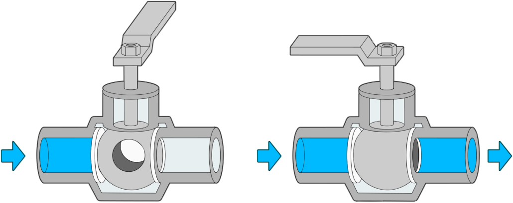
Ball valves operate based on a simple mechanism. They have a ball with a central hole. When open, the hole aligns with the pipeline, permitting fluid passage. When shut, the ball rotates, blocking fluid movement.

Ball vavve

MATERIALS AND THEIR PROS & CONS :Actuator a

Different applications demand various materials. Let’s delve into some standard material choices:

    • Brass:
      • Pros: Corrosion-resistant, cost-effective, and widely available.
      • Cons: Not ideal for highly corrosive surroundings.
    • Stainless Steel:
      • Pros: Excellent for high-temperature settings due to its corrosion resistance and durability.
      • Cons: Pricier than brass and might not be best for quick temperature shifts.
    • Carbon Steel:
      • Pros: Durable and suitable for high pressures.
      • Cons: Corrosion-prone in certain conditions.
    • PTFE (Polytetrafluoroethylene):
      • Pros: Highly resilient and chemical resistant.
      • Cons: Not the best for high-pressure scenarios.

HIGH-PRESSURE BALL VALVES :

Designed for extreme pressures, these are apt for critical tasks in sectors dealing with aggressive fluids. Trunnion ball valves are a top choice here, often found in the oil, gas, and power generation fields.

3-WAY VS. 2-WAY BALL VALVES :

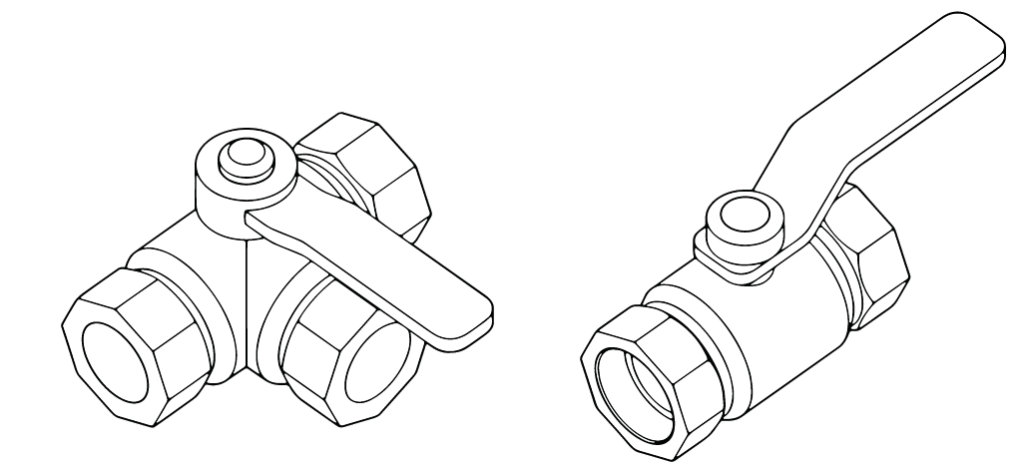
    • 3-Way Ball Valves: With three ports, they’re essential for tasks like mixing or distributing. In HVAC systems, they manage hot and cold water flow.
    • 2-Way Ball Valves: Two ports make them ideal for complete shut-off or passage.

Ball valve

AUTOMATED BALL VALVES :

Equipped with actuators for remote handling, these are perfect for industrial tasks, water treatment, and any situation demanding frequent or distant valve management. Electric, pneumatic, or hydraulic actuators can boost efficiency and lessen manual interference.

APPROVALS :

Specific industries might need certifications for safety and standard adherence. Common approvals include API 6D, API 607, ISO 9001, ISO 14001, and CE for Europe.

CONCLUSION :

Ball valves are pivotal in fluid flow management, providing a plethora of choices for diverse applications. Grasping their various forms, operation mechanics, material preferences, and suitability for different pressures ensures professionals make educated valve selections. Be it for general use, high pressures, or automation, the right ball valve promises peak performance, reliability, and security across a variety of domains and tasks.

Valve limit switchboxes are key parts in factories, helping control and monitor valve positions. This guide explains how these boxes are classified and how they work.

UNDERSTANDING VALVE SWITCHBOXES :

A valve limit switchbox keeps track of a valve’s position. It sends this data to a control system or person. These boxes come in many styles to fit different needs.

CLASSIFICATION OF VALVE LIMIT SWITCHBOXES :

  1. Mechanical Limit Switchboxes:
    • These use physical contact to sense the valve’s position.
    • A lever connected to the valve turns on a switch, sending data to the control system.
  2. Inductive Limit Switchboxes:
    • These use sensors close to the valve to detect its position.
    • A magnetic field reacts with a metal target on the valve, sending a signal when they’re close.
  3. Magnetic Limit Switchboxes:
    • These use magnets and sensors to find out where the valve is.
    • The magnet’s field changes as the valve moves, helping the sensor figure out the position.

WORKING PRINCIPLE OF VALVE LIMIT SWITCHBOXES :

All these switchboxes share a common way of working:

  1. Position Sensing:
    • The box always checks the valve’s position.
    • When the valve moves, it triggers a mechanism in the switchbox.
  2. Signal Transmission:
    • The box sends an electrical signal when the valve reaches a set point.
    • This signal goes to a control system to show the valve’s status.
  3. Feedback and Control:
    • The control system uses this data to make choices.
    • For instance, it can stop the valve when it’s fully open or closed.

ADVANTAGES OF VALVE LIMIT SWITCHBOXES :

These switchboxes bring several good points to system control:

  • Accuracy: They give precise and reliable info about valve positions, avoiding mistakes.
  • Remote Monitoring: People can check valve positions from afar, saving time and effort.
  • Emergency Shutdown: In emergencies, these boxes help make quick, safe choices.

CONCLUSION :

Valve limit switchboxes are vital for keeping industrial processes safe and efficient. Knowing how they’re classified and how they work helps people choose the right one for their needs. These switchboxes improve valve performance, boost safety, and make operations more smooth.

Managing the flow of liquids, gases, and steam in industries is essential. One tool that does this job exceptionally well is the single-acting pneumatic angle seat valve.

CONSTRUCTION AND DESIGN :

  • Materials: These valves are mainly made of stainless steel and other materials that don’t easily corrode.
  • Design: They come with a special angled seat. This ensures that when open, fluids flow smoothly.
  • Actuator: Found at the valve’s top, it uses compressed air. This part is the key to opening and closing the valve.

HOW THEY WORK :

  1. At Rest (Closed): The valve blocks fluid flow by default.
  2. Using Air (Open): Add compressed air to the actuator, and the valve opens, letting fluids flow.
  3. Stop Air (Closed): When the compressed air is gone, the valve closes again.

WHY THESE VALVES ARE EXCELLENT :

  1. Total Control: They give great control over fluid flows, helping keep processes stable.
  2. Quick Action: Thanks to the air power, they open and close swiftly.
  3. Energy Savers: They don’t use a lot of power, which means lower costs.
  4. Built to Last: Made sturdy, they don’t need changing or fixing often.

WHERE WE FIND THEM USEFUL :

  • Eating and Drinking: Controls flows when making or packaging food and drinks.
  • Making Medicine: Used in the processes that create drugs.
  • Clean Water: Found in places that treat water to make it clean.
  • Keeping Temperatures Right: In systems that heat or cool buildings.
  • Factory Machines: Common in systems that use machines to do tasks automatically.

CONCLUSION :

Single-acting pneumatic angle seat valves are vital tools in many industries. They’re loved for their ability to control flows precisely, react quickly, save energy, and last a long time. Using them means smoother processes, saving money, and less worry about repairs or replacements.

Solenoid valves are crucial in systems for fluid control. They come in two main types: pilot-operated and direct-acting. This guide dives into how they work, their differences, and where to use each.

WHAT ARE SOLENOID VALVES : 

A solenoid valve uses electric current to move a sealing element, like a plunger or diaphragm, and control fluid flow.

HOW DO SOLENOID VALVES WORK :

Here’s how these valves operate:

  • De-Energized State: When not powered, the valve is in its default position—either open or closed.
  • Energization: Applying current to the coil creates a magnetic field, moving the plunger or diaphragm.
  • Fluid Flow: The sealing element’s movement controls the fluid flow.
  • De-Energized Again: Removing the current brings the sealing element back to its default position.

TYPES OF SOLENOID VALVES :

Based on design, solenoid valves can be:

  • 2-Way: One inlet and one outlet; good for on/off control.
  • 3-Way: One inlet and two outlets; used for fluid direction change.
  • 4-Way: Two inlets and outlets; used for complex flow control.

PILOT-OPERATED VALVES :

These valves use a small pilot valve to control a main valve. When powered, the pilot valve opens, controlling the main valve via fluid pressure.

DIRECT-OPERATED VALVES :

Direct-acting valves work without a pilot valve. The coil’s magnetic field directly moves the sealing element.

DIFFERENCES BETWEEN PILOT-OPERATED AND DIRECT-ACTING :

  • Pressure: Pilot-operated can handle higher pressures.
  • Flow: Pilot-operated is better for high-flow applications.
  • Speed: Direct-acting valves respond quicker.
  • Power: Direct-acting usually uses less energy.

WHERE ARE SOLENOID VALVES USED :

These valves are used in:

  • Automotive: For controlling fuel and transmission fluid.
  • HVAC: To manage refrigerant and air flows.
  • Water Treatment: Essential for controlling water and chemicals.
  • Industrial Automation: For precise flow control.
  • Medical Equipment: To control gases and liquids in critical processes.

CONCLUSION :

Choosing between pilot-operated and direct-acting valves depends on your needs, like flow rates and pressure. These valves are key in many industries for efficient, precise fluid control.

Pneumatic actuators play an essential role in a multitude of industrial applications, converting compressed air into mechanical motion. These devices come in several designs, but one of the most fundamental distinctions is between single acting and double acting actuators. This guide delves deep into their operation, advantages, and best-fit scenarios.

PNEUMATIC ACTUATORS : THE FUNDAMENTALS

  • Functionality: Pneumatic actuators utilize compressed air to produce motion, which can be linear or rotational based on the design.
  • Control Mechanism: Actuators respond to pressure differentials in a control system, where compressed air is either introduced or vented from actuator chambers to generate motion.

SINGLE ACTING VS. DOUBLE ACTING ACTUATORS

  • Single Acting : These actuators use compressed air to move the actuator in one direction (either to open or close). A spring or external force is typically used to return the actuator to its original position. They are often referred to as “spring return” or “fail-safe” actuators because they return to a default position in case of air supply failure.

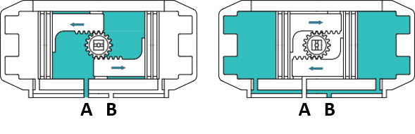
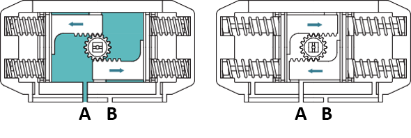
Air to port A forces the pistons outwards, causing the springs to compress, The pinion turns counterclockwise while air is being exhausted from port B.

Loss of air pressure on port A, the stored energy in the springs forces the pistons inwards. The pinion turns clockwise while air is being exhausted from port A.

  • Double Acting: Double acting actuators use compressed air to move the actuator in both the opening and closing directions. They have two air ports to alternately apply pressure for open and close actions. Without air pressure, a double acting actuator will stay in its last position.

double acting Actuator

Air to Port A forces the pistons outwards, causing the pinion to turn counterclockwise while the air is being exhausted from Port B.

Air to Port B forces the pistons inwards, causing the pinion to turn clockwise while the air is being exhausted from Port A.

ADVANTAGES OF PNEUMATIC ACTUATORS :

  1. Energy Efficient: Only require air, making them optimal when air is available.
  2. Safe: Ideal for explosive environments due to the absence of sparks.
  3. Cost-Effective: Lower operational costs when compressed air is accessible.
  4. Rapid Response: Especially with single acting designs, the response time can be swift due to the spring mechanism.

WHERE THEY SHINE :

  • Single Acting: Best for safety-critical applications where default positions are vital during failures.
  • Double Acting: Essential for processes that require more precise control in both directions and where air supply is consistent.

TECHNICAL CONSIDERATIONS :

  • Force & Speed: Pneumatic actuators, especially double acting types, can provide fast actuation. Their force output is determined by the air pressure and actuator size.
  • Environmental Suitability: They excel in environments prioritizing cleanliness or safety, devoid of electricity or harmful fluids.

CONCLUSION :

In the realm of actuation, the choice of actuator has profound implications. Pneumatic actuators, specifically the distinction between single and double acting, cater to various applications based on their inherent advantages. A thorough understanding of their mechanics and functionalities enables industries to optimize performance and safety.

WORKING PRINCIPLE OF BUTTERFLY VALVE

Butterfly valves, known for their simple design, are quarter-turn valves that can be utilized for both on/off and throttling control. They primarily consist of a rotating disc, which is mounted on a shaft. The rotation of this disc, whether parallel or perpendicular to the flow, allows or restricts the flow of the fluid. The valve’s sealing mechanism works by the disc pressing tightly against the valve seat.

Depending on their mounting style, butterfly valves can be classified into:

  • Wafer Butterfly Valves: These are sandwiched between pipe flanges, and the connecting bolts encircle the valve body. Wafer butterfly valves are predominantly recommended for low-pressure applications.
  • Lug Butterfly Valves: These are quite similar to wafer valves but come with threaded holes. They can be secured from both ends using bolts. Additionally, these can also serve as end-of-line valves.
  • Flanged Butterfly Valves: Featuring standard ANSI flanges at both ends, these types of valves are bolted directly to the pipe.

TYPES OF BUTTERFLY VALVE DESIGNS

Butterfly valves can be categorized based on their design into:

  • Concentric Design: The most widely used design where the disc rotation is aligned with the stem and pipe axis. They’re economical and apt for water treatment and crude oil systems.
  • Double Offset Design: The stem is positioned slightly behind the disc’s centerline, reducing wear and tear during closing. This type finds its application mainly in chemical processes.
  • Triple Offset Design: Introducing a third offset, these types of valves minimize wear by allowing minimal contact until the valve is fully closed. They’re primarily used for high-temperature and extreme-pressure scenarios.

ACTUATION METHODS FOR BUTTERFLY VALVES

The operation of butterfly valves can be either manual or automatic:

  • Manual Actuation: Often done using hand levers for smaller valves or gearboxes for larger ones.
  • Electric Actuation: Uses an electric motor for turning the valve stem, perfect for automated systems.
  • Pneumatic Actuation: Employs compressed air for movement, offering fast operation and fail-safe capabilities.
  • Hydraulic Actuation: Utilizes hydraulic pressure, suitable for high-pressure scenarios and precise control.

APPLICATIONS OF BUTTERFLY VALVES

From water treatment to food processing, butterfly valves have a plethora of applications:

  • Water Treatment: Mainly used for regulating flow.
  • Oil and Gas: Control flow in crude oil pipelines.
  • Chemical Processing: Ideal for managing flow of chemicals.
  • Pharmaceuticals: Precision flow control is vital.
  • Food Processing: Their hygienic design makes them apt.
  • Fire Protection: Control water flow and pressure effectively.
  • HVAC Systems: Regulate flow of air and water.
  • Marine: Corrosion-resistant properties come into play.
  • General Industrial: For versatile and cost-effective flow control.

CONCLUSION :

Butterfly valves, with their simplicity and reliability, remain a top choice across many industries. Their specific design and actuation method should align with the application’s requirements, considering factors like pressure, temperature, and flow rate.